
Air compressor having quick coupling device

a technology of air compressor and quick coupling, which is applied in the direction of hose connection, piston pump, positive displacement liquid engine, etc., to achieve the effect of quick coupling and attaching, quick and changeable attachment, and quick disengagemen

Active Publication Date: 2012-10-30
CHOU WEN SAN
View PDF10 Cites 30 Cited by
  • Summary
  • Abstract
  • Description
  • Claims
  • Application Information

AI Technical Summary

Benefits of technology

Enables rapid and secure attachment and detachment of various facilities to the air compressor's outlet tube, enhancing flexibility and usability by allowing different facilities to be easily connected and disconnected as needed.

Problems solved by technology

However, normally, the outlet ports include a predetermined coupling structure for attaching and securing the predetermined parts or elements or attachments or facilities, but may not be used for attaching and securing the other parts or elements or attachments or facilities, and the parts or elements or attachments or facilities may not be changed with each other or may not be changeably attached and secured to different outlet ports of the outlet tube of the cylinder housing.

Method used


Image

  • Air compressor having quick coupling device
  • Air compressor having quick coupling device
  • Air compressor having quick coupling device

Examples


Embodiment Construction

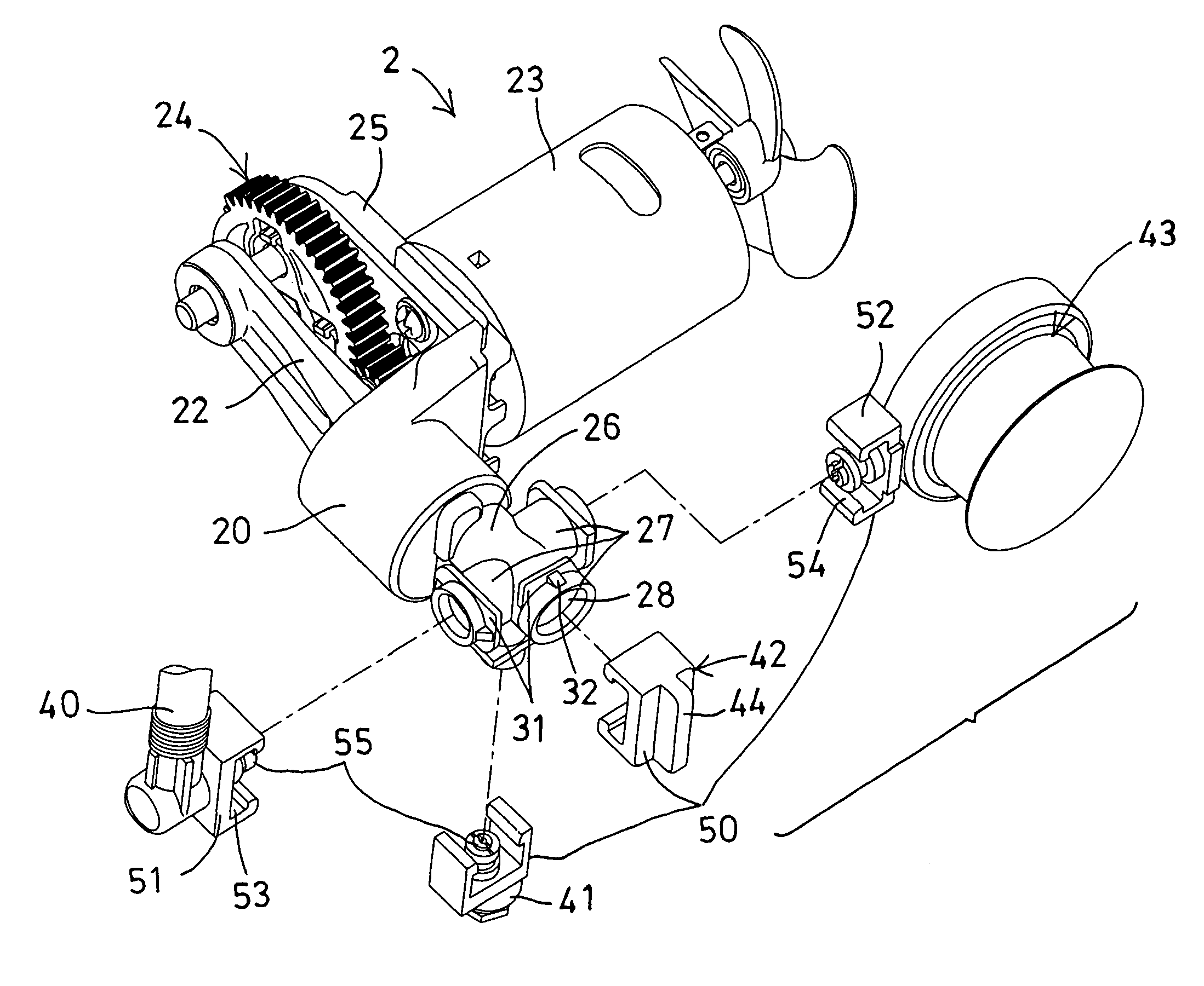
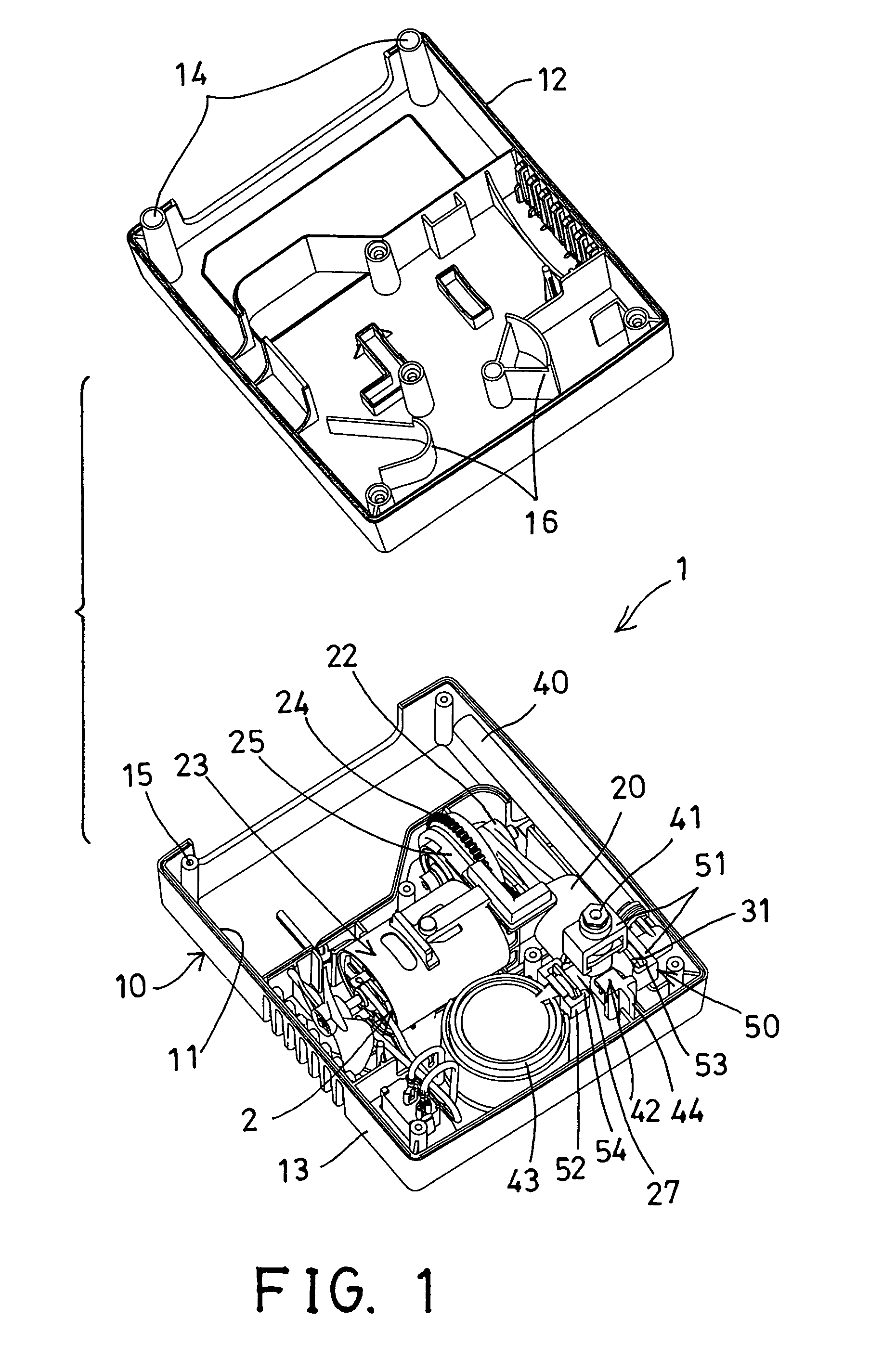
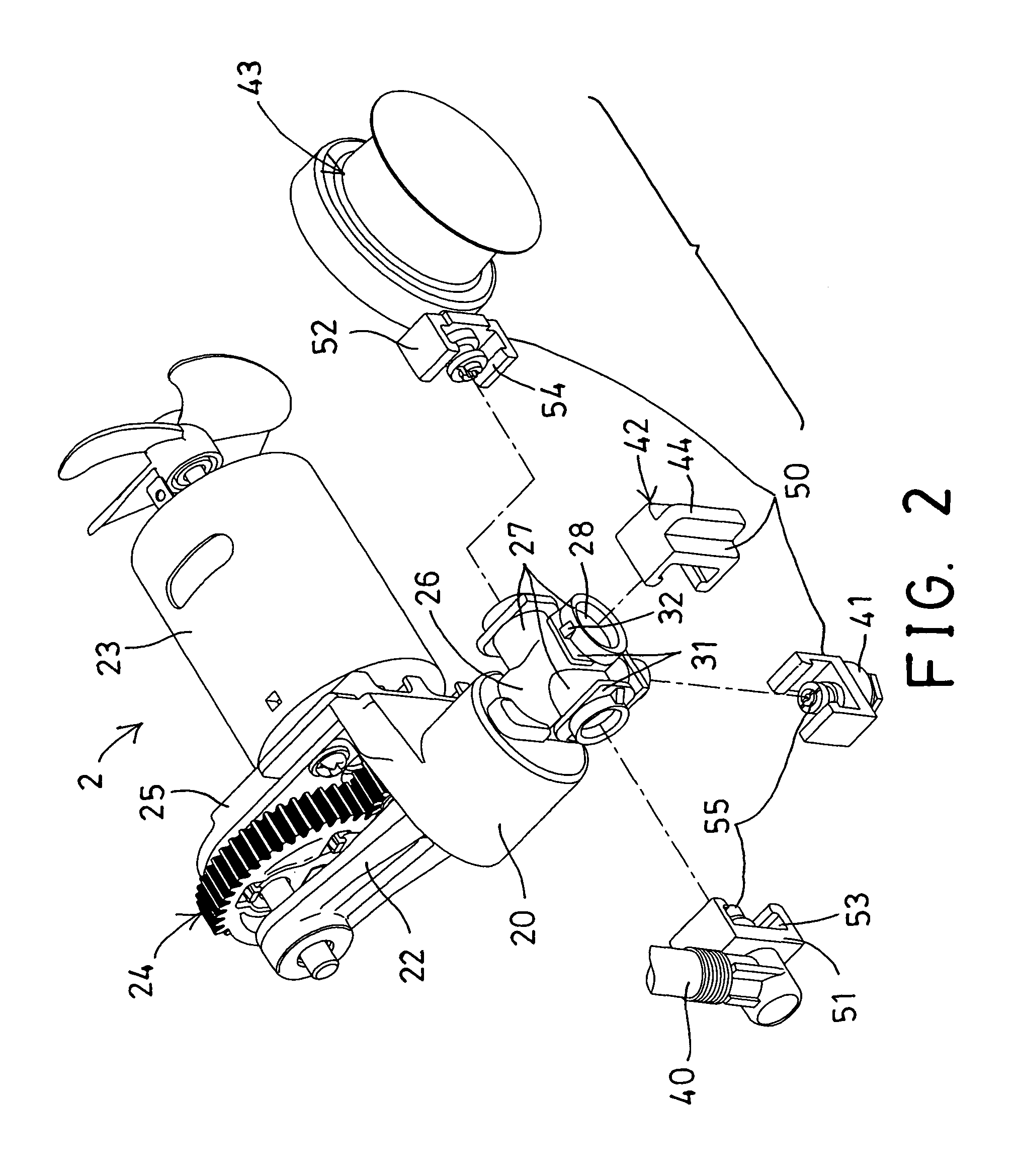
[0023]Referring to the drawings, and initially to FIGS. 1-4, an air compressing assembly 1 in accordance with the present invention comprises an outer receptacle 10 including a chamber 11 formed therein and formed or defined by a lower receptacle member 12 and an upper receptacle member 13, in which the receptacle members 12, 13 each include one or more studs 14, 15 formed or provided therein and aligned with or engageable with each other for engaging with the latches or locks or fasteners (not shown), and for detachably securing the receptacle members 12, 13 together and for closing the chamber 11 of the receptacle 10 and for stably retaining the parts or elements or attachments or facilities in the chamber 11 of the receptacle 10.

[0024]An air compressing device 2 includes a cylinder housing 20 received and attached and secured in the chamber 11 of the receptacle 10, a piston 21 (FIG. 4) slidably engaged in the cylinder housing 20, a piston rod 22 attached or secured to or extended...


PUM


Abstract

An air compressing device includes a piston slidably engaged in a cylinder housing and driven by a motor to generate a pressurized air, the cylinder housing includes an outlet tube, and an outlet port extended from the outlet tube, and an anchor plate extended from the outlet port, and a facility includes a coupler for engaging with the outlet port and the anchor plate and for quickly and detachably securing the coupler and the facility to the outlet port of the outlet tube and for allowing the pressurized air to be supplied to the facility. The facility is selected from a hose, a relief valve, a pressure gauge, or a cover, and the coupler includes a C-shaped structure.

Description

BACKGROUND OF THE INVENTION[0001]1. Field of the Invention[0002]The present invention relates to an air compressor, and more particularly to an air compressing device including a quick coupling device for quickly coupling and attaching and securing various parts or elements or attachments or facilities to an outlet tube of the air compressor and also for quickly disengaging the parts or elements or attachments or facilities from the air compressor and thus for allowing the parts or elements or attachments or facilities to be quickly and changeably attached and secured to the outlet tube of the air compressor.[0003]2. Description of the Prior Art[0004]Various kinds of typical air compressing devices have been developed by the applicant and comprise a cylinder housing, a piston slidably received in the cylinder housing, and a motor coupled or attached to the cylinder housing and coupled to the piston for moving the piston relative to the cylinder housing in a reciprocating action, in ...

Claims


Application Information

Patent Timeline
Patent Type & Authority Patents(United States)
IPC IPC(8): F04B41/02F04B35/00F16L37/00
CPCF04B35/008F04B35/01F04B35/04F04B39/123
Inventor CHOU, WEN SAN
Owner CHOU WEN SAN
Learn More