
Controlling apparatus for a concentration photovoltaic system

a control apparatus and photovoltaic system technology, applied in the field of photovoltaic systems, can solve the problems of difficult maintenance of such solar trackers, no way to take advantage of the highest intensity, and inability to meet the requirements of high-intensity measurements

Inactive Publication Date: 2012-10-30
INST NUCLEAR ENERGY RES ROCAEC
View PDF10 Cites 8 Cited by
  • Summary
  • Abstract
  • Description
  • Claims
  • Application Information

AI Technical Summary

Benefits of technology

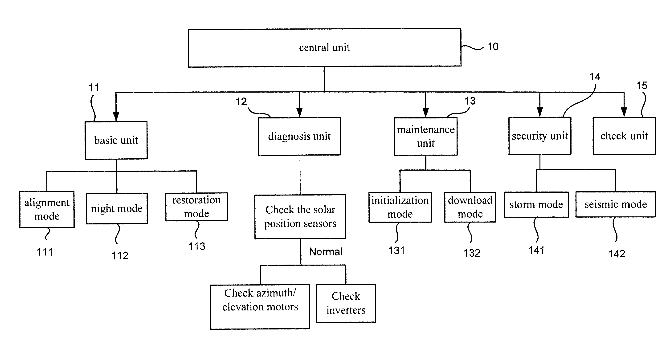
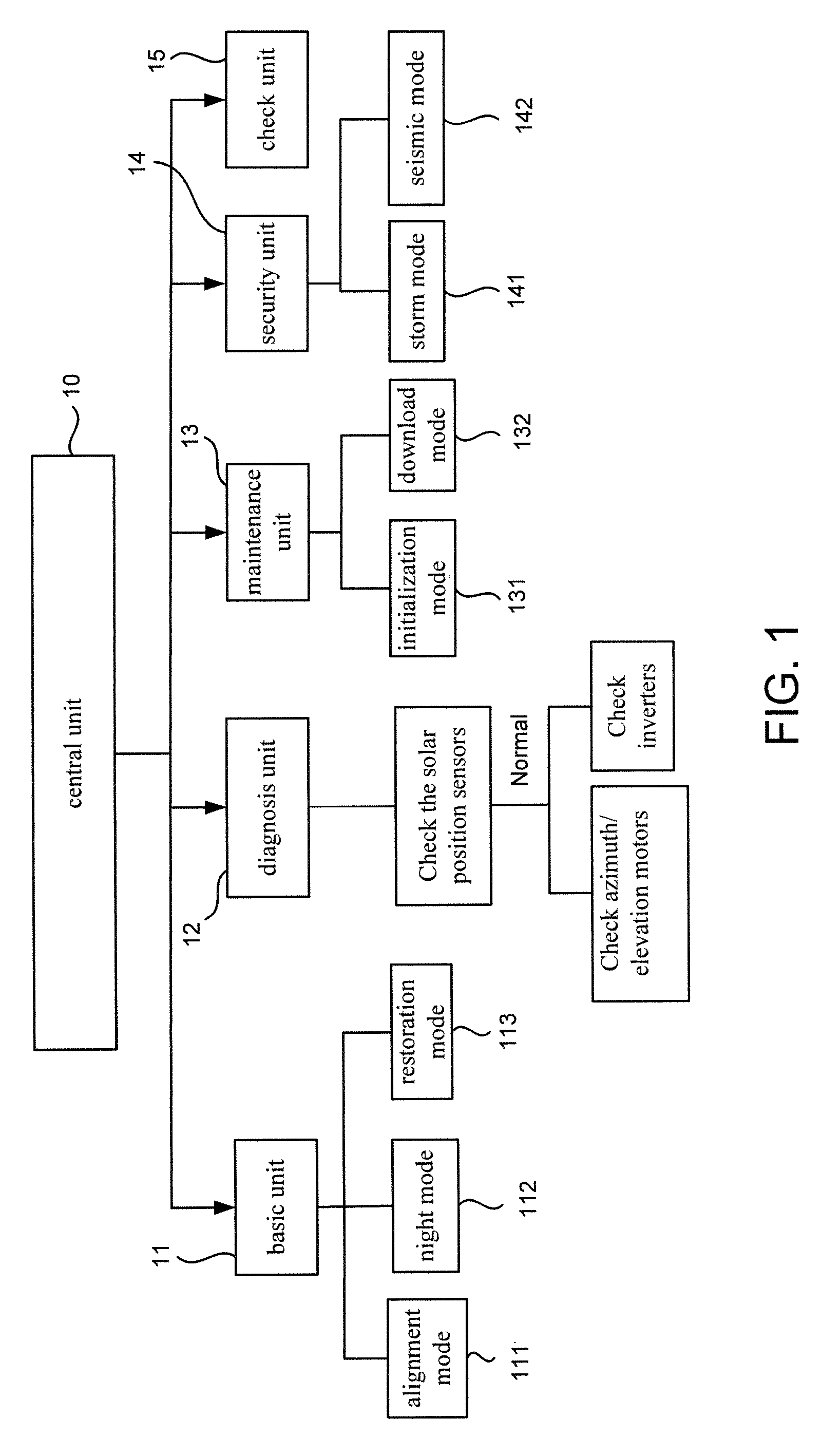
"The present invention provides a controlling apparatus for a photovoltaic system including a solar cell array, an inverter, and a solar tracker. The apparatus includes a central unit, a basic unit, a diagnosis unit, a maintenance unit, a security unit, and a check unit. The basic unit determines the direction of driving the solar tracker and controls it in the alignment mode, the night mode, and the restoration mode. The diagnosis unit checks the solar position sensor, the motors, and the inverter. The maintenance unit acquires data of errors and downloads control programs. The security unit controls the solar tracker in the storm mode and the seismic mode. The check unit synchronizes the clock of the solar tracker controller with a built-in clock. The technical effects of the invention include improved efficiency and accuracy of solar cell array alignment, improved safety and security, and improved synchronization of clocks."

Problems solved by technology

Therefore, there is no way to take the advantage of the highest intensity of the sunlight at any given time of a day.
The structures of such solar trackers are often complicated.
The maintenance of such solar trackers is difficult and often requires technicians.
Moreover, current photovoltaic systems are limited to direct use, without monitoring the optimal respondent angle and direct normal angle in a certain place on the earth and the efficiency of the conversion of direct currents into alternating currents with inverters.
The layouts of the current photovoltaic systems are not optimal, and the maintenance is difficult and requires a lot of resources and high costs.

Method used


Image

  • Controlling apparatus for a concentration photovoltaic system
  • Controlling apparatus for a concentration photovoltaic system
  • Controlling apparatus for a concentration photovoltaic system

Examples


Embodiment Construction

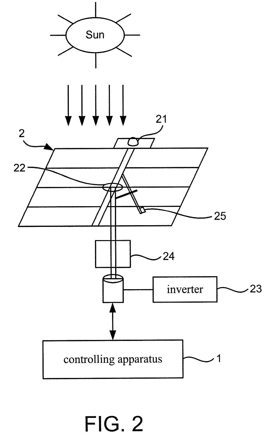
[0012]Referring to FIG. 2, a solar tracker 2 for use in a photovoltaic system includes a solar position sensor 21, a controller 24 connected to the solar position sensor 21, a first motor 22 connected to the controller 24 and a second motor 25 connected to the controller 24. The solar position sensor 21 senses the sunlight and sends signals to the controller 24. Based on the signals, the controller 24 determines the azimuth and elevation of the sun relative to a place on the earth where the photovoltaic system is located. Based on the azimuth of the sun, the controller 24 instructs the first motor 22 to rotate a solar cell array of the photovoltaic system. According to the elevation of the sun, the controller 24 instructs the second motor 25 to tilt the solar cell array. An inverter 23 is connected to the solar cell array. A controlling apparatus 1 according to the preferred embodiment of the present invention is connected to the solar tracker 2.

[0013]Referring to 1, the controlling...


PUM


Abstract

Disclosed is a controlling apparatus for use in a photovoltaic system. The photovoltaic system includes a solar cell array, an inverter and a solar tracker. The solar tracker includes a solar position sensor, a controller connected to the solar position sensor, a first motor connected to the controller for rotating the solar cell array according to the azimuth of the sun and a second motor connected to the controller for tilting the solar cell array according to the elevation of the sun. The controlling apparatus includes a central unit, a basic unit, a diagnosis unit, a maintenance unit, a security unit and a check unit.

Description

FIELD OF THE INVENTION[0001]The present invention relates to a photovoltaic system and, more particularly to a controlling apparatus for use in a photovoltaic system including a solar tracker and a solar cell array.DESCRIPTION OF THE RELATED ARTS[0002]The azimuth and elevation of the sun relative to a place on the earth change during a day. A conventional photovoltaic system includes a solar cell array. The solar cell array cannot be aligned to the sun based on the spin of the earth. Therefore, there is no way to take the advantage of the highest intensity of the sunlight at any given time of a day.[0003]There have been devised solar trackers for photovoltaic systems to track the sun and align the photovoltaic system to the sun. Such a solar tracker includes a frame, a first motor, a second motor, a controller and a sensor. The frame supports a solar cell array. The first motor drives the frame and therefore changes the azimuth of the solar cell array. The second motor drives the fr...

Claims


Application Information

Patent Timeline
Patent Type & Authority Patents(United States)
IPC IPC(8): H01L31/042G05D3/00F24S50/20
CPCF24J2/38F24J2/542G01S3/7803G01S3/7861Y02E10/47F24S30/452F24S50/20H02S20/32Y02E10/50
Inventor CHYOU, SHANG-LEELUNG, I-TAOYANG, SHIU-JU
Owner INST NUCLEAR ENERGY RES ROCAEC
Learn More