
Fiber optic cable assemblies with furcation bodies having features for manufacturing and methods of making the same

a technology of fiber optic cable and assembly, which is applied in the direction of optical elements, manufacturing tools, instruments, etc., can solve the problems of cumbersome detachment of installed furcation assemblies and reattaching them to fiber optic equipment, inability to easily integrate securing techniques into fiber optic equipment and/or not securely mount, and inability to achieve high-density fiber optic equipment design

Inactive Publication Date: 2012-10-16
CORNING OPTICAL COMM LLC
View PDF9 Cites 31 Cited by
  • Summary
  • Abstract
  • Description
  • Claims
  • Application Information

AI Technical Summary

Benefits of technology

The patent describes fiber optic cable assemblies that have a fiber optic cable attached to a furcation body. The furcation body has features that make it easier to manufacture the cable assembly, such as features that prevent rotation and allow for inspection during manufacturing. The furcation body can also have a weep hole to allow air bubbles to escape. The cable assembly can be secured using a clip or inhibited from moving sideways when mounted in fiber optic equipment. Overall, the invention provides a more efficient and reliable way to attach fiber optic cables to equipment.

Problems solved by technology

However, high-density fiber optic equipment designs may not be possible due to the inability of the fiber optic equipment to support a sufficient density of furcation assemblies.
However, these securing techniques may not be easily integrated into fiber optic equipment and / or not securely mount the furcation assembly.
Also, if changes or reconfigurations of fiber optic cables or optical connections in already installed fiber optic equipment are necessary, it may be cumbersome to detach installed furcation assemblies and reattach them to the fiber optic equipment.
Further, these securing techniques may affect the stability and strength of the furcation assembly attachment to fiber optic equipment, including the ability of the furcation plug to withstand lateral and rotational forces.

Method used


Image

  • Fiber optic cable assemblies with furcation bodies having features for manufacturing and methods of making the same
  • Fiber optic cable assemblies with furcation bodies having features for manufacturing and methods of making the same
  • Fiber optic cable assemblies with furcation bodies having features for manufacturing and methods of making the same

Examples


Embodiment Construction

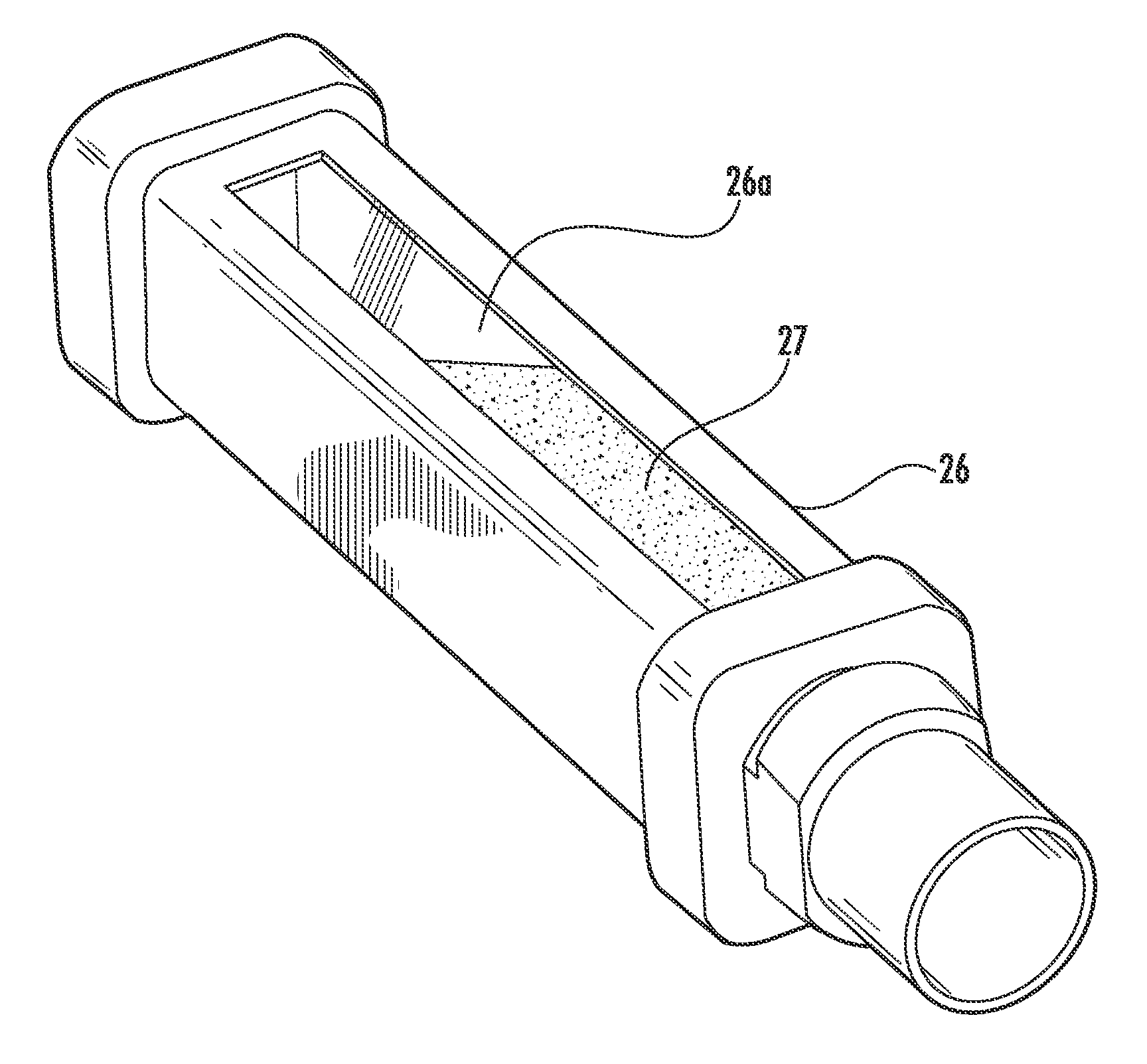
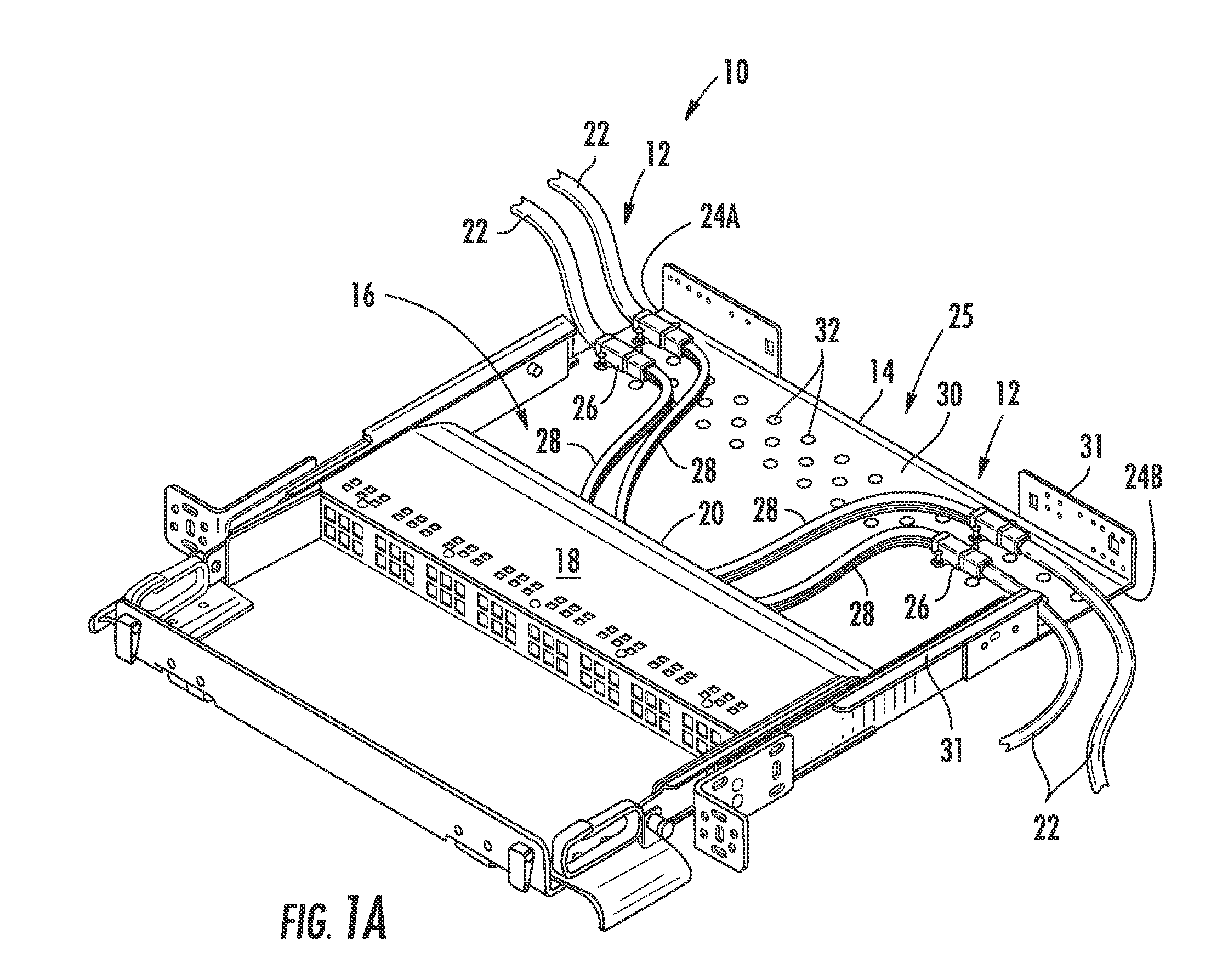
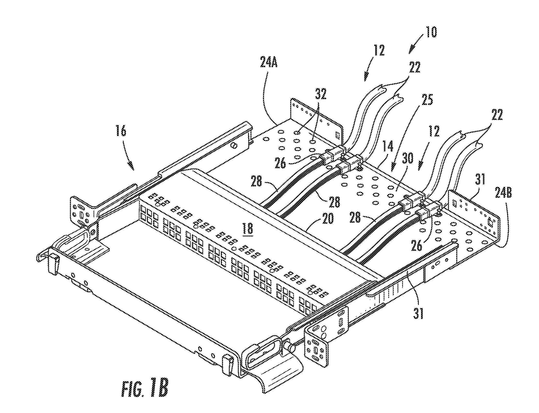
[0006]Disclosed are fiber optic cable assemblies having a fiber optic cable attached to a furcation body that includes features that are advantageous for manufacturing. The fiber optic cable is received into the furcation body and furcated into one or more furcated legs that extend from the furcation body and filled with an epoxy or adhesive. The furcated legs can have any suitable configuration such as individual buffered optical fibers, upjacket legs, ribbon, etc. Further, the furcated legs can have any suitable lengths such as staggered lengths to avoid slack storage issues and / or equal lengths. The furcation body includes an anti-rotation feature integrated therein for inhibiting rotation of the furcation body when mounted in or to fiber optic equipment and includes at least one viewing port, thereby allowing inspection during manufacturing. In other embodiments, the furcation body of the fiber optic cable assembly includes at least one weep hole for allowing air bubbles / air poc...


PUM

PropertyMeasurementUnit
sizeaaaaaaaaaa
distance L4aaaaaaaaaa
distance L5aaaaaaaaaa

Abstract

Fiber optic cable assemblies having furcation bodies with features that are advantageous for manufacturing are disclosed along with methods of making the same. The furcation body include at least one anti-rotation feature for mounting the furcation body and a viewing portion and / or weep hole. The viewing portion is advantageous since it allows the observation during filling of the cavity with an epoxy, adhesive, or the like to strain relieve components of the fiber optic cable assembly within the furcation body. Simply stated, the viewing portion is translucent or clear for observing the filling of the furcation body and detecting if an air bubbles / air pockets are formed so that they can be reduced and / or eliminated. The furcation body may also have a weep hole for allowing air bubbles / air pockets to escape. Additionally, the furcation body of the fiber optic cable assembly may be secured within a clip or other suitable structure for mounting the same.

Description

RELATED APPLICATIONS[0001]The present application is a Continuation-in-Part (CIP) of U.S. patent application Ser. No. 12 / 487,929 filed on Jun. 19, 2009 and titled “Clip For Securing A Fiber Optic Cable Assembly and Associated Assemblies,” which is a Continuation-in-Part (CIP) of U.S. patent application Ser. No. 12 / 417,325 filed on Apr. 2, 2009 and titled “Fiber Optic Cable Assemblies Employing a Furcation Body Having Anti-Rotation Feature,” which claims priority to U.S. Provisional Patent Application Ser. Nos. 61 / 197,068 filed Oct. 23, 2008 and 61 / 190,538 filed Aug. 29, 2008, all of the disclosures of which are incorporated herein by reference in their entirety.BACKGROUND[0002]The technology of the disclosure relates to fiber optic cable assemblies having a furcation body along with assemblies using the same.TECHNICAL BACKGROUND[0003]Benefits of optical fiber use include extremely wide bandwidth and low noise operation. Because of these advantages, optical fiber is increasingly bein...

Claims


Application Information

Patent Timeline
Patent Type & Authority Patents(United States)
IPC IPC(8): G02B6/36G02B6/00
CPCG02B6/4471Y10T29/4998G02B6/4453G02B6/4452G02B6/44526G02B6/44528
Inventor BARLOWE, EDWARD K.COOKE, TERRY L.DEAN, JR., DAVID L.KLAVUHN, TORY A.WALTERS, JEFFERY M.
Owner CORNING OPTICAL COMM LLC
Learn More