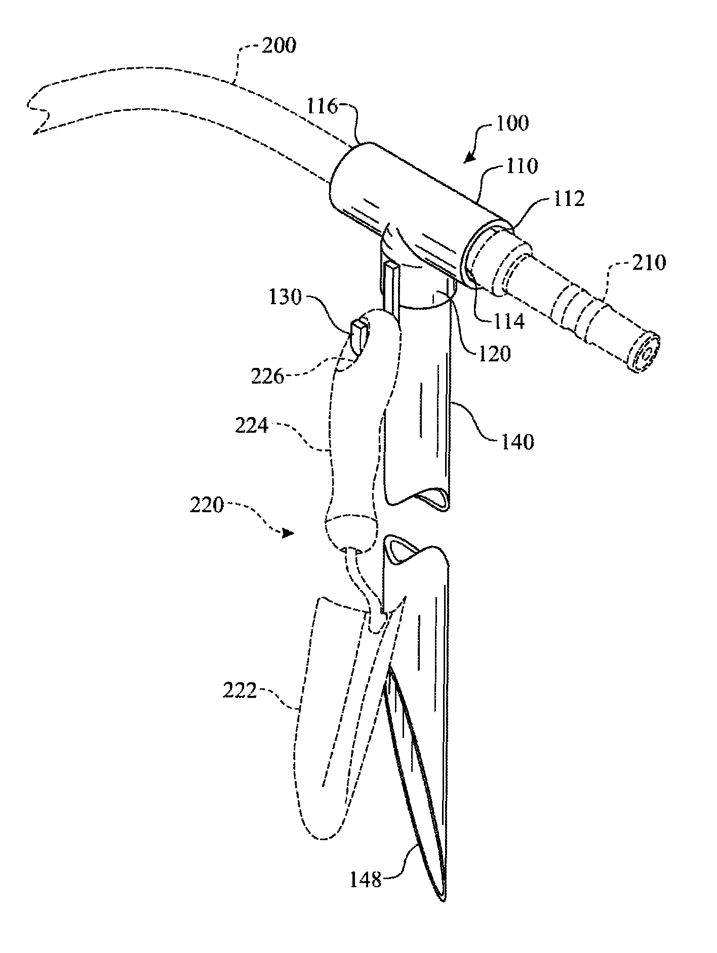
Water hose support apparatus

a technology for holding a garden hose and a support device, which is applied in the direction of mechanical devices, machine supports, other domestic objects, etc., can solve the problems of affecting the use of water hoses. , to achieve the effect of facilitating the use of water hoses, the user is free to us

Active Publication Date: 2012-10-16
SCHWANEBEK GLEN
View PDF18 Cites 15 Cited by
  • Summary
  • Abstract
  • Description
  • Claims
  • Application Information

AI Technical Summary

Benefits of technology

[0031]inserting said hose nozzle through said horizontal rigid tube segment such that an exterior surface of said hose nozzle remains in frictional engagement with said interior surface of said horizontal rigid tube segment, thereby maintaining said hose nozzle in an orientation horizontally,

Problems solved by technology

Many conventional hose supports are difficult to engage with and disengage from the hose body and may result in its damage, particularly if the hose is of the relatively thin walled, inexpensive garden hose type.
Much time may be lost in fixing the support in place and in removing it when the hose is needed for other purposes.
Moreover, certain of such devices are relatively complicated and expensive to make and repair.
Others of such devices are solely adapted to engage hose nozzles of certain sizes and shapes and are not capable of operating when a different type of attachment is connected to the hose to be suspended therewith above ground level.
Such devices do not provide positive support for the attachment.
This apparatus is cumbersome to use, particularly when the water supply is turned on, as the nozzle has to be removed from the hose to configure the holder.
The apparatus is limited in that the coil turns apply a compression force to the garden hose.
Inserting the hose between two adjacent coils may be difficult.
This apparatus is limited in that the design requires the individual to hold the device during use.
The individual can resort to holding the hose with their hands, between their knees or using any other manual means which is generally less than optimal.

Method used


Image

  • Water hose support apparatus
  • Water hose support apparatus
  • Water hose support apparatus

Examples


Embodiment Construction

[0044]The following detailed description is merely exemplary in nature and is not intended to limit the described embodiments or the application and uses of the described embodiments. As used herein, the word “exemplary” or “illustrative” means “serving as an example, instance, or illustration.” Any implementation described herein as “exemplary” or “illustrative” is not necessarily to be construed as preferred or advantageous over other implementations. All of the implementations described below are exemplary implementations provided to enable persons skilled in the art to make or use the embodiments of the disclosure and are not intended to limit the scope of the disclosure, which is defined by the claims. For purposes of description herein, the terms “upper”, “lower”, “left”, “rear”, “right”, “front”, “vertical”, “horizontal”, and derivatives thereof shall relate to the invention as oriented in FIG. 1. Furthermore, there is no intention to be bound by any expressed or implied theo...


PUM


Abstract

A hose holder assembly comprising a hose holder member being attached to an elongated hose holder support member. The hose holder member includes a tubular body having a passage therethrough for receiving a garden hose. The length of the body is sufficient to maintain the garden hose in a fixed position when subjected to forces resulting from a discharging flow of water. A body coupler section is provided for assembling the body to the support member. The coupler can be a male or female form factor. A utility hook can be included as a feature of the hose holder member for temporarily holding tools or other items. The body can be segmented into a fixed portion, which is attached to the support member and a removable portion, which removably engages with the fixed portion. A sizing sleeve can be offered to reduce a passage diameter for receiving hoses having smaller diameters.

Description

FIELD OF THE INVENTION[0001]The present disclosure generally relates to an apparatus and method for holding a garden hose. More particularly, the present disclosure relates to a tubular member affixed in a horizontal orientation to a top end of a vertically oriented support member, wherein a garden hose is inserted through the hollow interior of the tubular member maintaining the hose in an operative position.BACKGROUND OF THE INVENTION[0002]A number of water hose supports are known. Each of these known supports is directed towards a means for temporarily maintaining a garden hose in an operative position for watering a flora. The hose support member maintains the hose in an operative position proximate the ground.[0003]Many conventional hose supports are difficult to engage with and disengage from the hose body and may result in its damage, particularly if the hose is of the relatively thin walled, inexpensive garden hose type. Much time may be lost in fixing the support in place a...

Claims


Application Information

Patent Timeline
IPC IPC(8): A01G25/00B05B15/06
CPCB05B15/062B05B15/622
Inventor SCHWANEBEK, GLEN
Owner SCHWANEBEK GLEN
Why Eureka
Try Eureka