
All-optical high bandwidth sampling device based on a third-order optical nonlinearity

a sampling device and optical nonlinearity technology, applied in the field of optical sampling, can solve the problems of increasing the difficulty of building rf waveguides and electronics that operate, the response time of practical devices is usually limited to 100 ghz or less, and the difficulty of directly measuring intensity variations at picosecond response times or faster

Inactive Publication Date: 2012-10-02
UNIV OF WASHINGTON CENT FOR COMMERICIALIZATION
View PDF4 Cites 34 Cited by
  • Summary
  • Abstract
  • Description
  • Claims
  • Application Information

AI Technical Summary

Benefits of technology

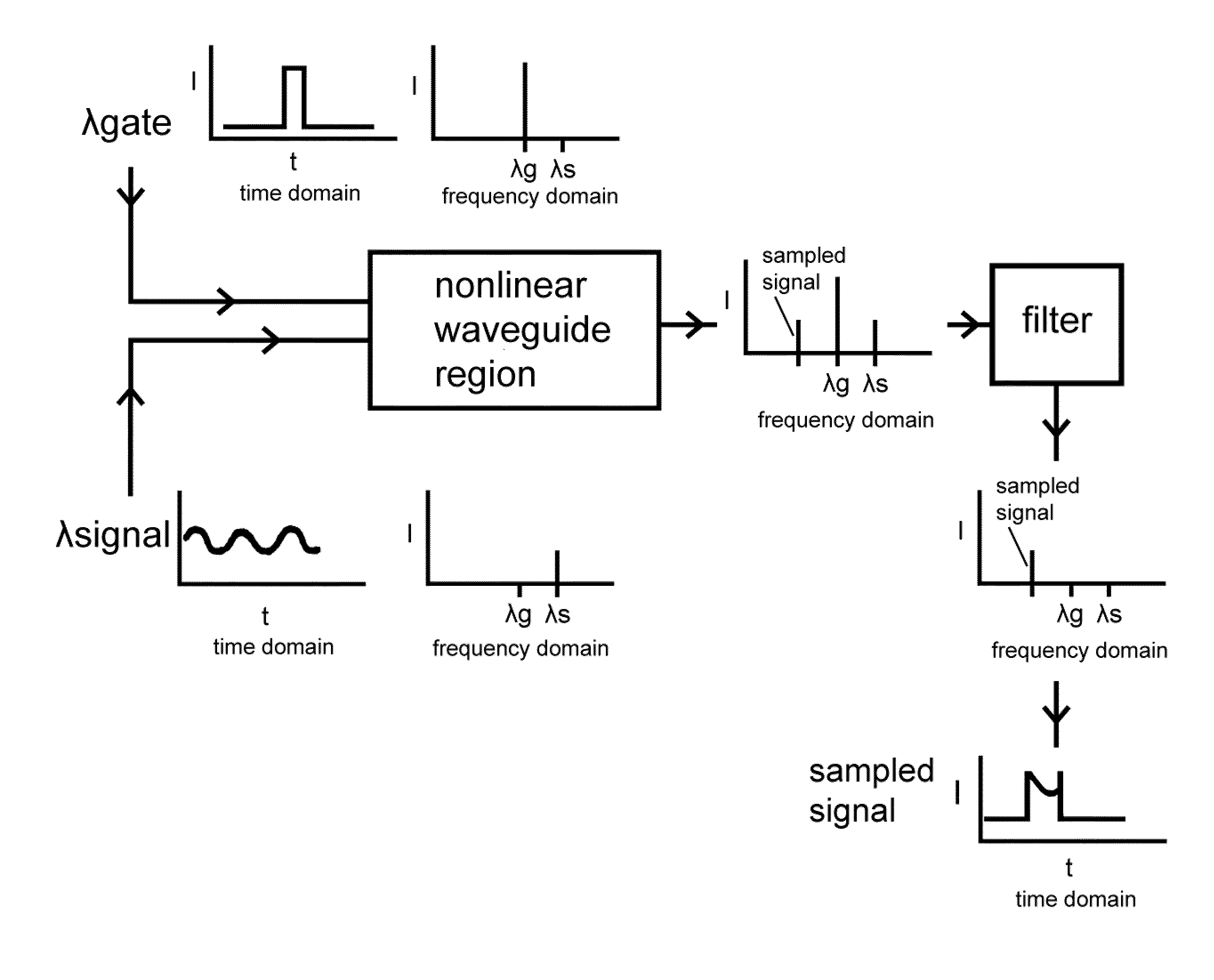
The invention is about an all-optical sampling device that uses a waveguide with a nonlinear waveguide region to sample signals of interest. The device includes a filter that is connected to the output of the waveguide with a nonlinear waveguide region. When a gate signal is applied, the device samples the signal of interest and produces a sampled signal at a different wavelength that is free of the gate signal. The nonlinear waveguide region can be a silicon waveguide or a ring waveguide, and the filter can also be a waveguide. The technical effect of this invention is that it allows for efficient and accurate optical sampling without the need for a separate gate signal.

Problems solved by technology

A challenge in characterizing such optical signals is the difficulty of directly measuring intensity variations at picosecond response times or faster.
As a result, responses for practical devices are usually limited to bandwidths of 100 GHz or less.
Another problem is the increasing difficulty of building RF waveguides and electronics that operate at speeds of 100 GHz and higher in an economical fashion.

Method used


Image

  • All-optical high bandwidth sampling device based on a third-order optical nonlinearity
  • All-optical high bandwidth sampling device based on a third-order optical nonlinearity
  • All-optical high bandwidth sampling device based on a third-order optical nonlinearity

Examples


Embodiment Construction

[0042]We now describe high index contrast waveguides that are useful to concentrate light in order to enhance nonlinear optical effects in various materials so that such effects can be employed to manipulate light (or more generally electromagnetic radiation) at low power levels, as compared to conventional systems and methods that employ nonlinear optical materials. The manipulation of electromagnetic radiation or light can be useful to provide a variety of components that perform operations on light such as rectification, modulation, filtering, and logic operations in a manner analogous to the same operations which are provided using electronic devices operating on electrical signals. For example, an input a light wave to be processed is impressed onto the component. The light wave has at least one parameter characterizing the light wave, such as one of an intensity, a polarization, a frequency, a wavelength, and a duration (e.g., a pulse length, or in the case of continuous wave ...


PUM

PropertyMeasurementUnit
roughnessaaaaaaaaaa
thickaaaaaaaaaa
e-folding depthaaaaaaaaaa

Abstract

An all-optical sampling device using four-wave mixing in third-order optically nonlinear materials is described. The four-wave mixing based sampler comprises a waveguide combiner, which adds a gate optical signal to a signal of interest to be sampled. In a four-wave mixing region, a sampled signal at the output optical frequency is produced. All of the optical signals are sent to a passive optical filter, which preferentially discards the gate and signal optical frequencies, but preserves the sampled signal at the output optical frequency. The sampled signal at the output optical frequency can be observed, displayed, recorded or otherwise manipulated.

Description

CROSS-REFERENCE TO RELATED APPLICATIONS[0001]This application claims priority to and the benefit of U.S. provisional patent application Ser. No. 61 / 145,451, filed Jan. 16, 2009, which application is incorporated herein by reference in its entirety.STATEMENT REGARDING FEDERALLY FUNDED RESEARCH OR DEVELOPMENT[0002]Not Applicable.THE NAMES OF THE PARTIES TO A JOINT RESEARCH AGREEMENT[0003]Not Applicable.INCORPORATION-BY-REFERENCE OF MATERIAL SUBMITTED ON A COMPACT DISC[0004]Not Applicable.FIELD OF THE INVENTION[0005]The invention relates to optical sampling in general and particularly to an all-optical sampling device that employs a material exhibiting large third-order optical non-linearity.BACKGROUND OF THE INVENTION[0006]A common situation in optical measuring systems is to encounter a very high bandwidth intensity modulation on an optical signal. This intensity variation could be the result of a high bandwidth modulator, or it could be the result of some sort of physical process th...

Claims


Application Information

Patent Timeline
Patent Type & Authority Patents(United States)
IPC IPC(8): G02B6/00G02F1/35
CPCG02F1/3536
Inventor BAEHR-JONES, TOMHOCHBERG, MICHAEL J.
Owner UNIV OF WASHINGTON CENT FOR COMMERICIALIZATION
Learn More