
Fixed focus lens and imaging system

a fixed focus lens and imaging system technology, applied in the field of lenses and imaging systems, can solve the problems of inability to adjust the projection system, the projection system adopting the plane screen may lack in-situ feel, and the projection distance may be too large, so as to reduce the effective pixel and illumination of the image, reduce the effect of geometrical distortion and large effective pixel number

Active Publication Date: 2012-10-02
YOUNG OPTICS
View PDF3 Cites 1 Cited by
  • Summary
  • Abstract
  • Description
  • Claims
  • Application Information

AI Technical Summary

Benefits of technology

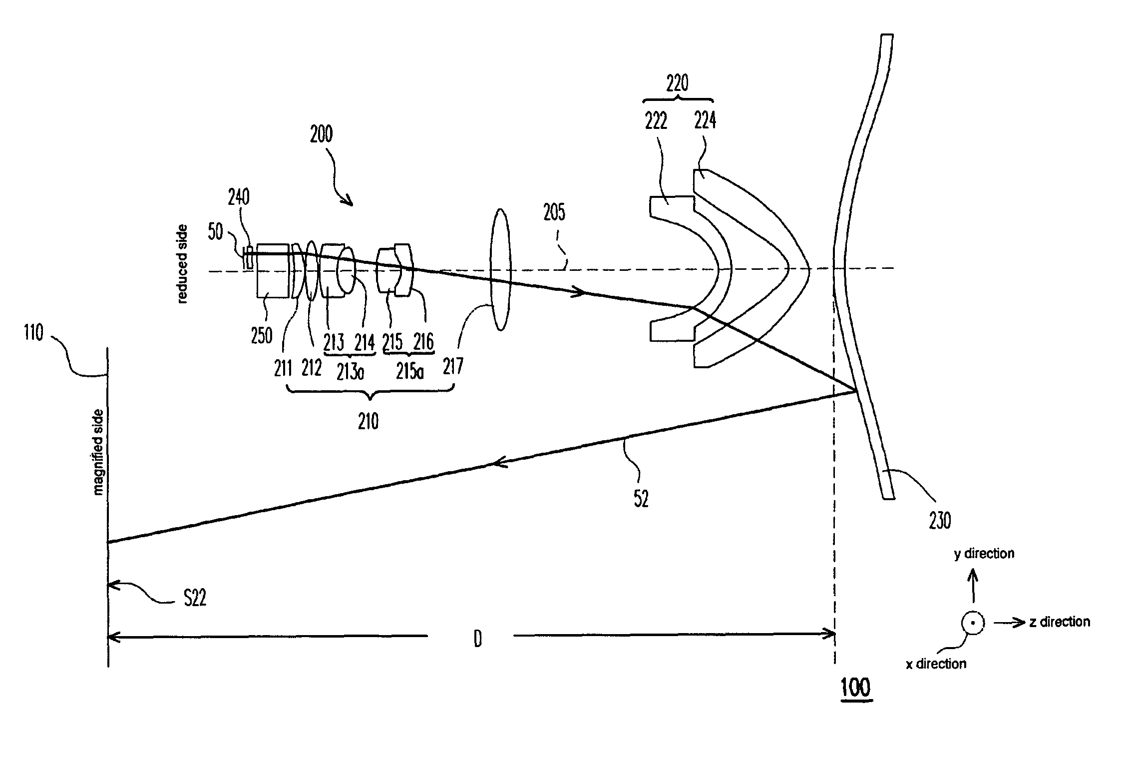
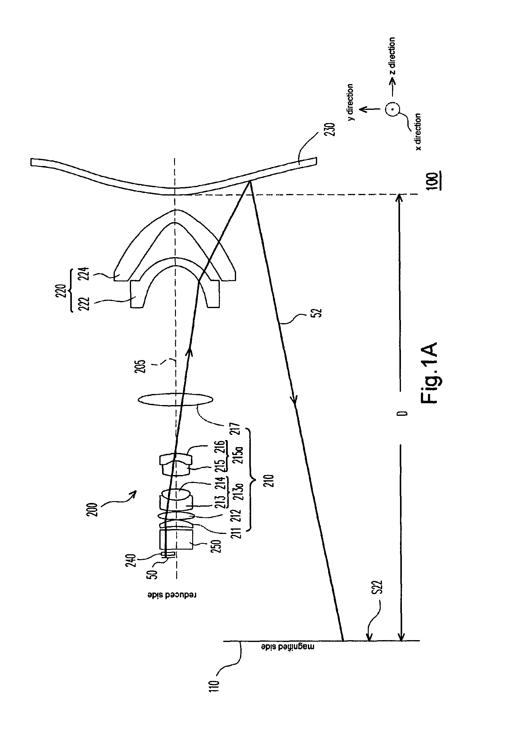
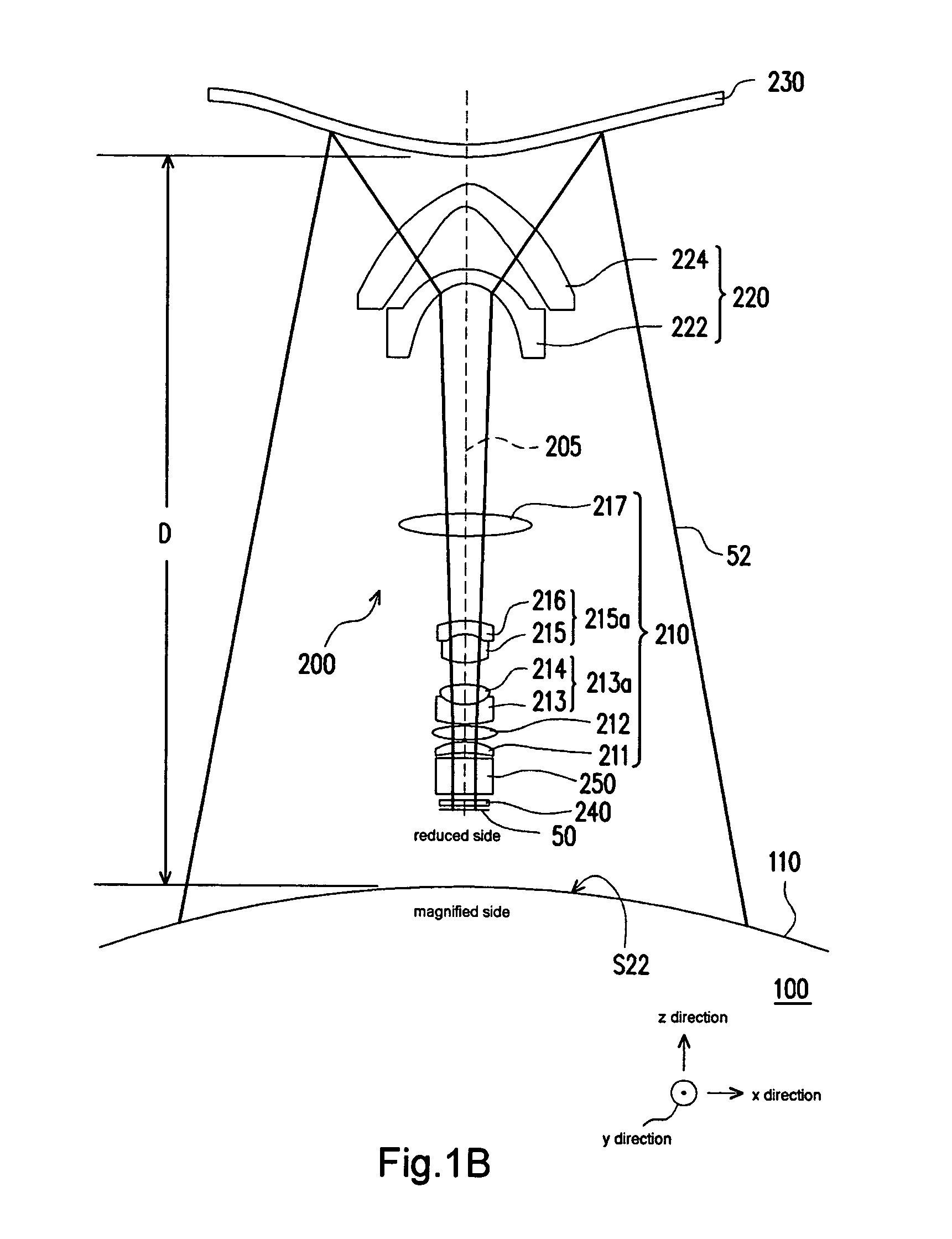
The invention provides a fixed-focus lens that can produce a curved image, which can be used in projection apparatus to increase the feel of the image. The lens has a first lens group, a second lens group, and a free form reflective mirror, with the second lens group including an aspherical lens and a concave-convex lens. The lens can be used in an imaging system with a curved screen, which results in a curved image with low geometric distortion, large effective pixel number, and high illumination. The technical effects of the invention include increased in-situ feel, reduced geometric distortion, and improved image quality.

Problems solved by technology

However, the projection systems adopting the plane screen may lack in-situ feel when the projection systems adopting the plane screen is used to a video conference.
However, the conventional projection systems adopt a conventional lens to project the light valve onto the curved screen, the imaging surface formed by the conventional lens is a plane, and the imaging surface may not coincide with the curved screen.
To solve the problem that the imaging surface may not coincide with the curved surface, some conventional technology adopts the projection lens with longer focus, but the technology may stretch the projection distance and make the projection system become too large.
In addition, because the imaging surface may not coincide with the curved screen, the image on the screen may generate geometric distortion.

Method used


Image

  • Fixed focus lens and imaging system
  • Fixed focus lens and imaging system
  • Fixed focus lens and imaging system

Examples


Embodiment Construction

[0027]In the following detailed description of the preferred embodiments, reference is made to the accompanying drawings which form a part hereof, and in which are shown by way of illustration specific embodiments in which the invention may be practiced. In this regard, directional terminology, such as “top,”“bottom,”“front,”“back,” etc., is used with reference to the orientation of the Figure(s) being described. The components of the present invention can be positioned in a number of different orientations. As such, the directional terminology is used for purposes of illustration and is in no way limiting. On the other hand, the drawings are only schematic and the sizes of components may be exaggerated for clarity. It is to be understood that other embodiments may be utilized and structural changes may be made without departing from the scope of the present invention. Also, it is to be understood that the phraseology and terminology used herein are for the purpose of description an...


PUM


Abstract

A fixed-focus lens capable of imaging a light valve disposed at a reduced side onto a magnified side is provided. The fixed-focus lens includes a first lens group, a second lens group, and a free form reflective mirror. The first lens group is disposed in the light path between the reduced side and the magnified side. The second lens group is disposed in the light path between the first lens group and the magnified side and includes a first free form lens. The free form reflective mirror is disposed in the light path between the second lens group and the magnified side. An imaging surface imaged from the light valve by the fixed-focus lens is a curved surface. An imaging system using the fixed-focus lens is also provided.

Description

CROSS-REFERENCE TO RELATED APPLICATION[0001]This application claims the priority benefit of Taiwan application serial no. 98122618, filed on Jul. 3, 2009.BACKGROUND OF THE INVENTION[0002]1. Field of the Invention[0003]The invention generally relates to a lens and an imaging system, and more particularly, to a fixed-focus lens and an imaging system having the fixed-focus lens.[0004]2. Description of Related Art[0005]With the development of display technology, new displays such as a liquid crystal display (LCD), a plasma display panel (PDP), and a projection apparatus have taken the place of the conventional cathode ray tub (CRT). The LCD, PDP, and other panel display may occupy larger domestic market as a result of the smaller thickness. However, the projection apparatus may provide a larger size image (more than 52 inches, for example) at a lower cost, so the projection apparatus may occupy certain market. In addition, the large size image may be seen by more people, so the projecti...

Claims


Application Information

Patent Timeline
Patent Type & Authority Patents(United States)
IPC IPC(8): G02B17/00
CPCG02B13/16G02B17/08
Inventor HSU, YA-LINGLIAO, LONG-SHENGCHEN, SUNG-NANCHEN, CHAO-SHUN
Owner YOUNG OPTICS
Learn More