
Anti-noise device for the air intake conduit of a supercharged internal combustion engine

a technology of anti-noise device and internal combustion engine, which is applied in the direction of combustion engine, combustion-air/fuel-air treatment, charge feed system, etc., can solve the problems of flow rate inversion, difficult, acoustic device is particularly sophisticated and expensive, and achieves simple and low-cost, satisfactory

Inactive Publication Date: 2012-10-02
MANN HUMMEL GMBH
View PDF9 Cites 3 Cited by
  • Summary
  • Abstract
  • Description
  • Claims
  • Application Information

AI Technical Summary

Benefits of technology

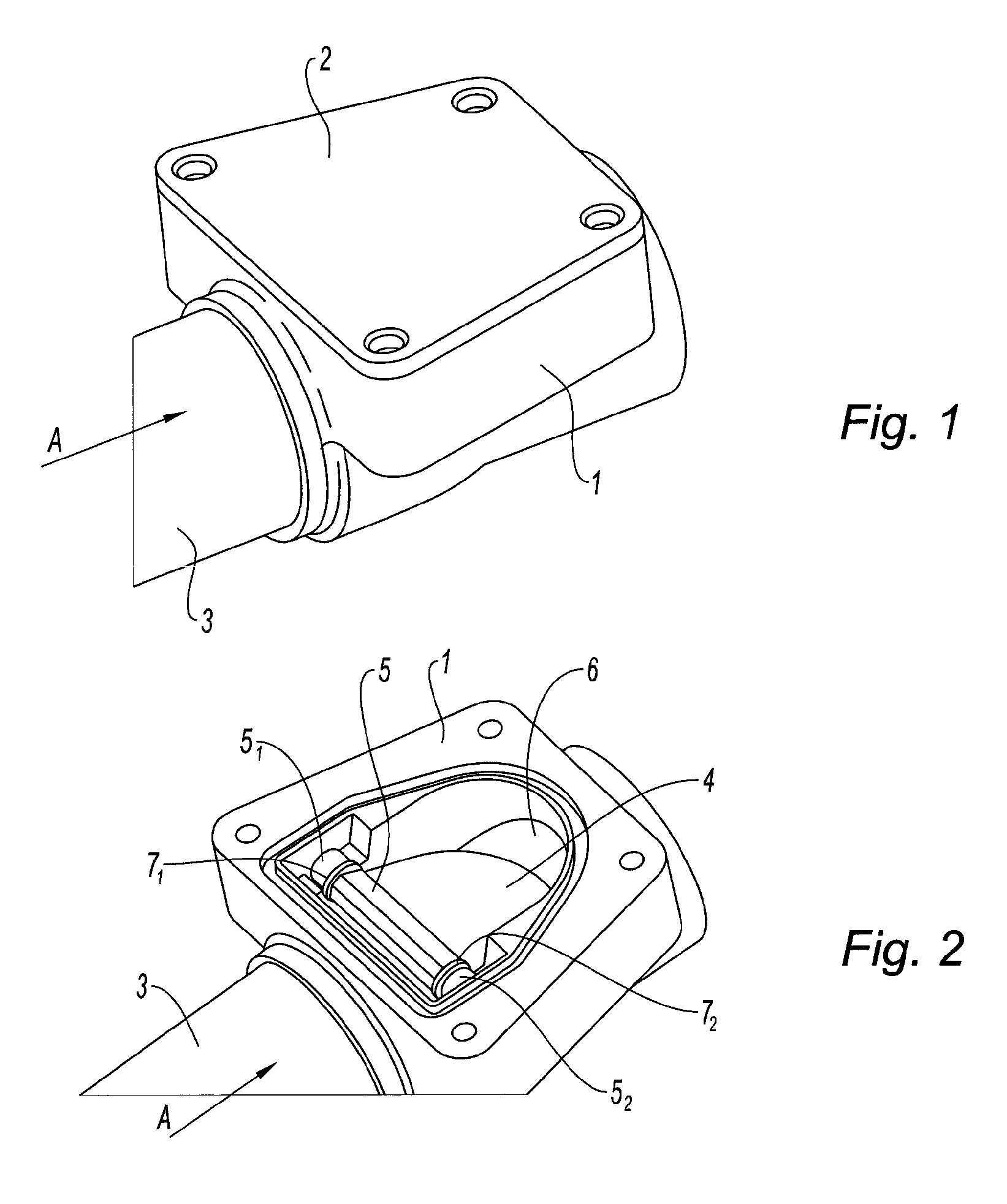
The present invention proposes an anti-noise device for an internal combustion engine that is simple, low-cost, and effective. The device is made up of a hinged flap that can close the air intake conduit of the engine, reducing the nuisance noises caused by surging phenomena from the compressor. The flap is designed to open up the conduit for airflow when there is no airflow force and close it when there is a force. The flap can be mounted in a housing case integrated into the air intake conduit, with a sealing joint between the case and cover to form an air-tight seal. Overall, this anti-noise device provides a simple and effective solution to reduce noise in internal combustion engines.

Problems solved by technology

It should in particular be noted that in supercharged internal combustion engines the compressor mounted in the air intake conduit can create aerodynamic instability phenomena causing flow rate inversions.
Now, these phenomena are sources of noises extending over a broad frequency band which are particularly bothersome and very difficult to reduce; this is even more difficult because they only appear late in the development cycle.
As a general rule these acoustic devices are particularly sophisticated and costly and furthermore are often insufficiently effective.

Method used


Image

  • Anti-noise device for the air intake conduit of a supercharged internal combustion engine
  • Anti-noise device for the air intake conduit of a supercharged internal combustion engine
  • Anti-noise device for the air intake conduit of a supercharged internal combustion engine

Examples


Embodiment Construction

[0027]Before describing in detail embodiments that are in accordance with the present invention, it should be observed that the embodiments reside primarily in combinations of apparatus components related to an anti-noise device for a turbocharged internal combustion engine. Accordingly, the apparatus components have been represented where appropriate by conventional symbols in the drawings, showing only those specific details that are pertinent to understanding the embodiments of the present invention so as not to obscure the disclosure with details that will be readily apparent to those of ordinary skill in the art having the benefit of the description herein.

[0028]In this document, relational terms such as first and second, top and bottom, and the like may be used solely to distinguish one entity or action from another entity or action without necessarily requiring or implying any actual such relationship or order between such entities or actions. The terms “comprises,”“comprisin...


PUM


Abstract

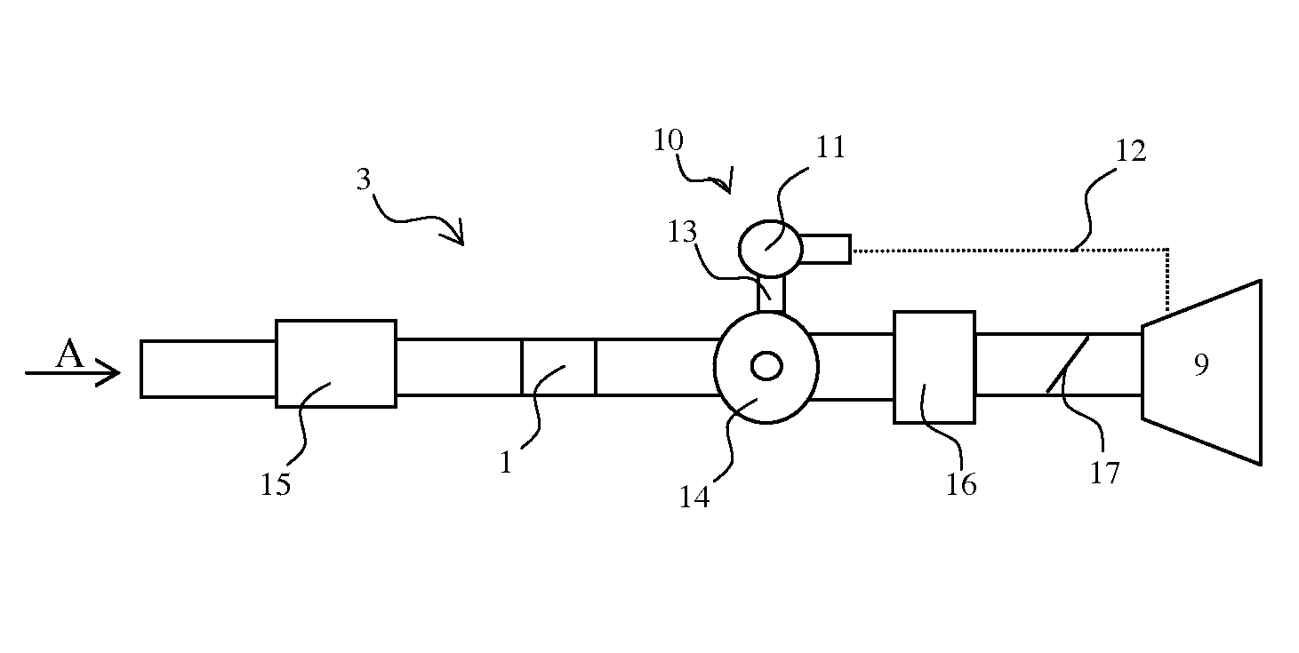
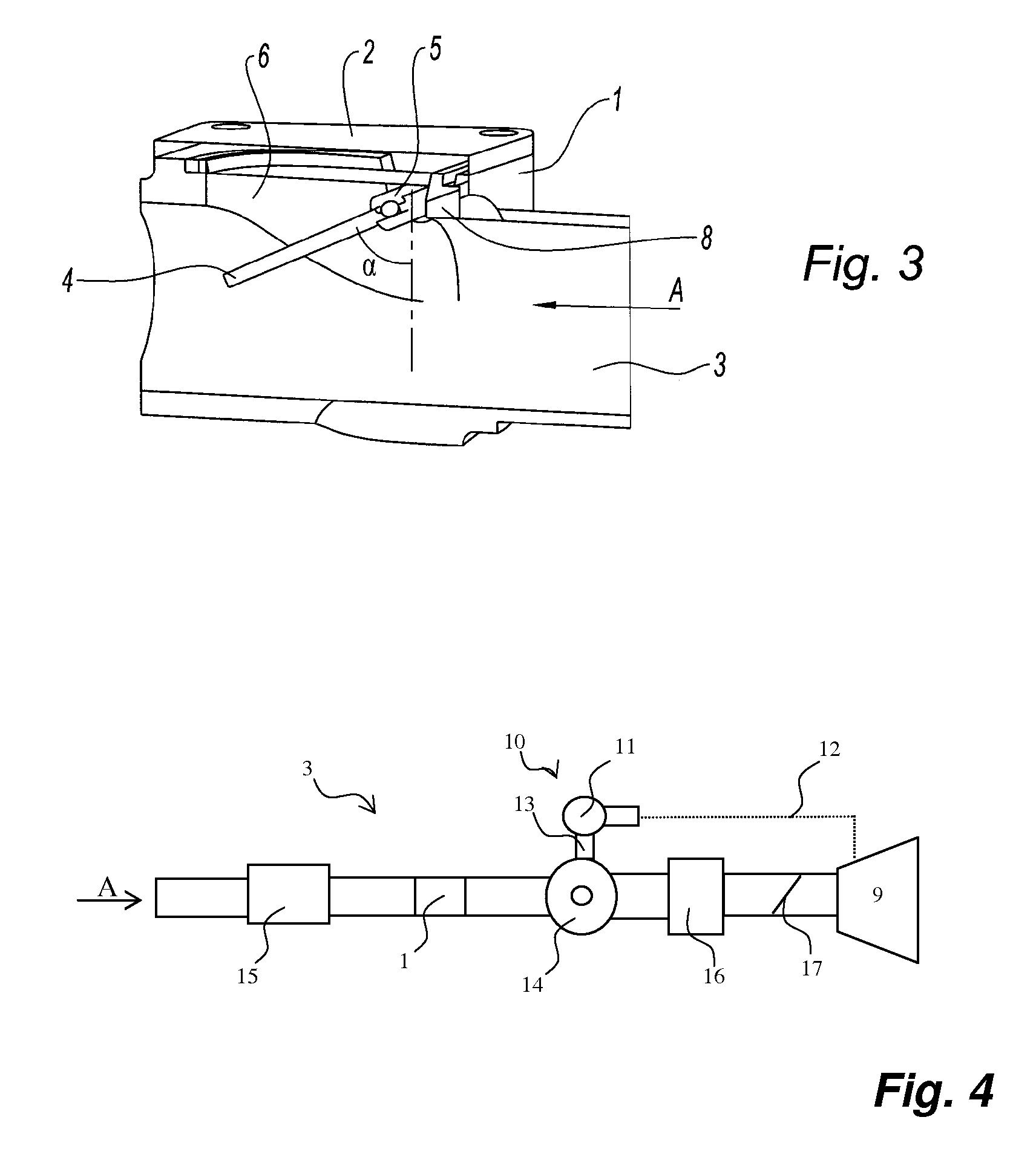
Anti-noise device for an internal combustion engine (9) equipped with a turbocompressor (10) for supercharging includes a turbine (11) placed in the exhaust gas flow and driven by these gases with the turbocompressor (10) connected by a shaft (13) to a compressor (14) mounted in the air intake conduit (3) of the engine (9). The anti-noise device includes a hinged flap (4) mounted within the air intake conduit (3) of the engine (9), upstream from the compressor (14) and capable of closing this conduit (3) under the action of a gaseous reflux coming towards it.

Description

CROSS REFERENCE TO RELATED APPLICATIONS[0001]This application claims the benefit under 35 USC 119 of French patent application 1051619 filed in France on Mar. 5, 2010, and which is hereby incorporated by reference in its entirety.TECHNICAL FIELD[0002]The invention relates to an anti-noise device for an internal combustion engine equipped with a turbocompressor for supercharging intake air which is composed of a turbine placed in the exhaust gas flow leaving this engine so as to be driven by these gases and connected by a shaft to a compressor mounted in the air intake conduit of the engine.BACKGROUND OF THE INVENTION[0003]Automobile manufacturers are currently concerned about lowering as much as possible the noise nuisances created by the engines of their vehicles.[0004]Many parts can be the source of such nuisances among which the following can be given as examples: air filter boxes, engine cases, cylinder head covers, compressors of turbocompressors for supercharging, etc.[0005]In...

Claims


Application Information

Patent Timeline
Patent Type & Authority Patents(United States)
IPC IPC(8): F02M35/12
CPCF02D9/103F02M35/10157F02M35/10275F02M35/10295F02M35/10301F02M35/1222F02B29/0406F02M35/10019Y02T10/144Y02T10/12
Inventor RAIMBAULT, VINCENTCORMERAIS, MICKAELCHAMPION, ARNAUD
Owner MANN HUMMEL GMBH
Learn More