Moving image reproducing apparatus
a technology of moving image and reproducing apparatus, which is applied in the direction of instruments, television systems, carrier indicating arrangements, etc., can solve the problems of insufficient compatibility between manufacturers, large time-consuming and labor-intensive, and inability to analyze data, etc., and achieve the effect of easy acquisition of information about a bit ra
- Summary
- Abstract
- Description
- Claims
- Application Information
AI Technical Summary
Benefits of technology
Problems solved by technology
Method used
Image
Examples
first exemplary embodiment
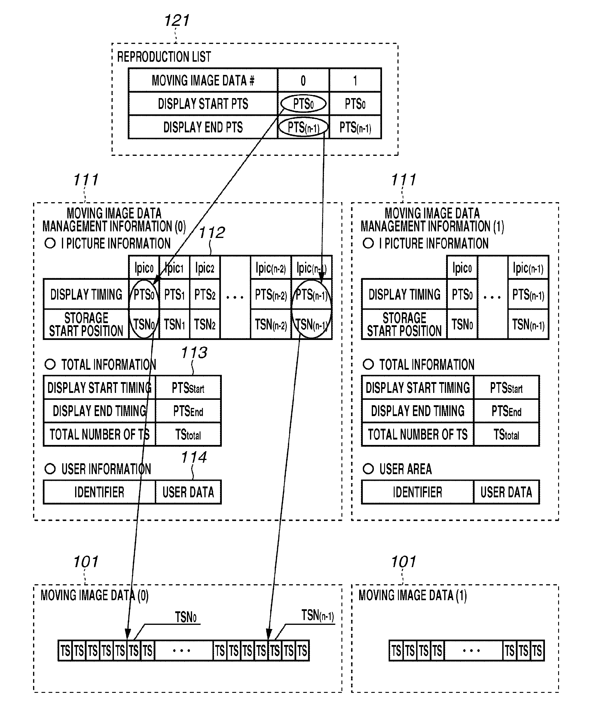
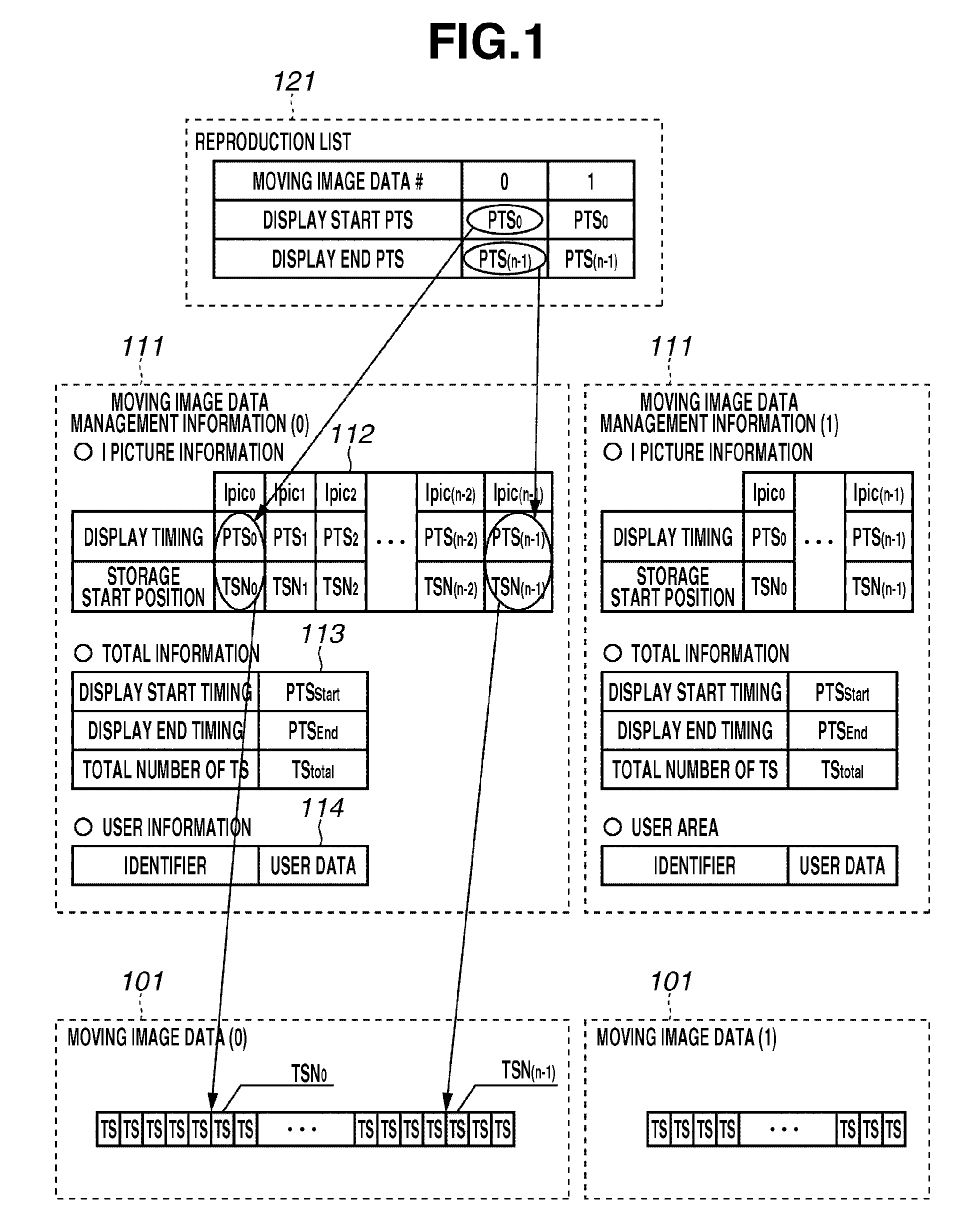
[0023]FIG. 1 illustrates an example of a recording format of moving image data reproduced by a reproducing apparatus according to a first exemplary embodiment of the present invention. The recording format is composed of three types of data, a reproduction list, moving image data management information, and moving image data.
[0024]The moving image data (n) 101 is data of moving image which is coded according to the H.264 / MPEG4-AVC standard and then multiplexed into transport streams (TS). Moving image data management information (n) 111 includes I picture information 112, total information 113, and user information 114 of the moving image data (n) 101 which are paired.
[0025]The I picture information 112 includes information about a presentation time stamp (PTS) which is timing information about each I picture in the moving image data (n) 101. The I picture information 112 includes information about a storage start packet number (i.e., a transport stream number (TSN)) of I pictures w...
second exemplary embodiment
[0050]According to the first exemplary embodiment, the bit rates for every intra picture are calculated and the calculation results are displayed. In a second exemplary embodiment, a maximum bit rate of an entire stream, especially, a stream with a variable bit rate (VBR) is calculated and displayed. Descriptions of the system configuration and procedures for creating the bit rate table are omitted as they are similar to those of the first exemplary embodiment.
[0051]FIG. 5 is a flowchart illustrating an example of processing procedures for calculating the maximum bit rate of the stream file using the bit rate table. Each of the processes illustrated in FIG. 5 is controlled by the processor 208.
[0052]In step S501, the processor 208 starts the process. In step S502, the processor 208 initializes a variable “j” and a field “MaxBitRate” to 0. The variable “j” represents an end line of the bit rate table. The field “MaxBitRate” is where the obtained maximum bit rate is stored.
[0053]Next,...
third exemplary embodiment
[0057]In a third exemplary embodiment, a method for calculating and displaying a recording mode (e.g., XP, SP, or LP mode) which determines an upper limit of the bit rate by which a video camera takes and records a stream, based on the maximum bit rate calculated according to the second exemplary embodiment is described. Descriptions of the system configuration and process for acquiring the “MaxBitRate” are omitted as they are similar to those of the second exemplary embodiment.
[0058]FIG. 6 illustrates an example of a relation between the maximum bit rate and the recording mode displayed using the OSD according to the present exemplary embodiment.
[0059]In FIG. 6, if the bit rate of 12 Mbps or more is acquired as the “MaxBitRate”, the “XP” is displayed as the appropriate recording mode using the OSD while the stream is being displayed. Similarly, if the bit rate of 5 Mbps or more but not exceeding 12 Mbps is acquired as the “MaxBitRate”, the “SP” is displayed using the OSD while the ...
PUM
 Abstract
Description
Claims
Application Information
 - R&D
- Intellectual Property
- Life Sciences
- Materials
- Tech Scout
- Unparalleled Data Quality
- Higher Quality Content
- 60% Fewer Hallucinations
Browse by: Latest US Patents, China's latest patents, Technical Efficacy Thesaurus, Application Domain, Technology Topic, Popular Technical Reports.
© 2025 PatSnap. All rights reserved.Legal|Privacy policy|Modern Slavery Act Transparency Statement|Sitemap|About US| Contact US: help@patsnap.com


