Electronic locking differential

a technology of differential locking and electronic components, applied in the direction of instruments, transportation and packaging, gearing, etc., can solve the problem of limited maximum axle/transaxle input torque (ait), and achieve the effect of reducing cumulative damage, rapid and controlled disengagement of the lock mechanism

Active Publication Date: 2012-09-11
FORD GLOBAL TECH LLC
View PDF30 Cites 5 Cited by
  • Summary
  • Abstract
  • Description
  • Claims
  • Application Information

AI Technical Summary

Benefits of technology

[0012]The control (i) reduces cumulate damage on the ELD locking mechanism, (ii) accommodates torsional displacement of the lock mechanism of an ELD due to control wheel differential speed and (iii) enables rapid, controlled disengagement of the lock mechanism when conditions for its disengagement are present. The strategy accounts for differential speed across the driven wheels, steering wheel angle, vehicle speed and the state of a manually operated switch used to select a desired state of the lock mechanism and differential.

Problems solved by technology

With the electronic locking differential engaged the maximum axle / transaxle input torque (AIT) is limited to the combined skid torque of the controlled wheels.

Method used


Image

  • Electronic locking differential
  • Electronic locking differential
  • Electronic locking differential

Examples


Embodiment Construction

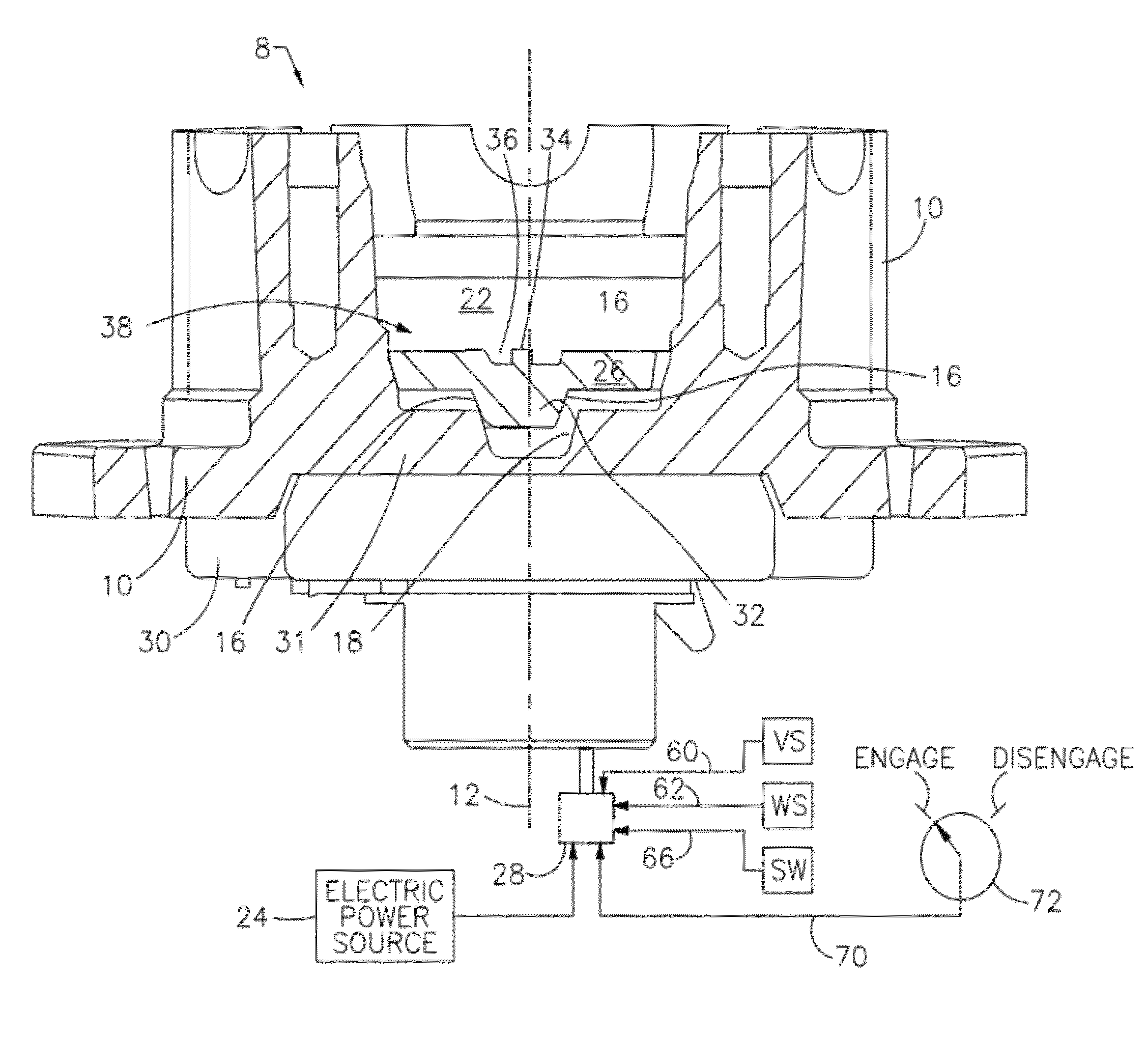
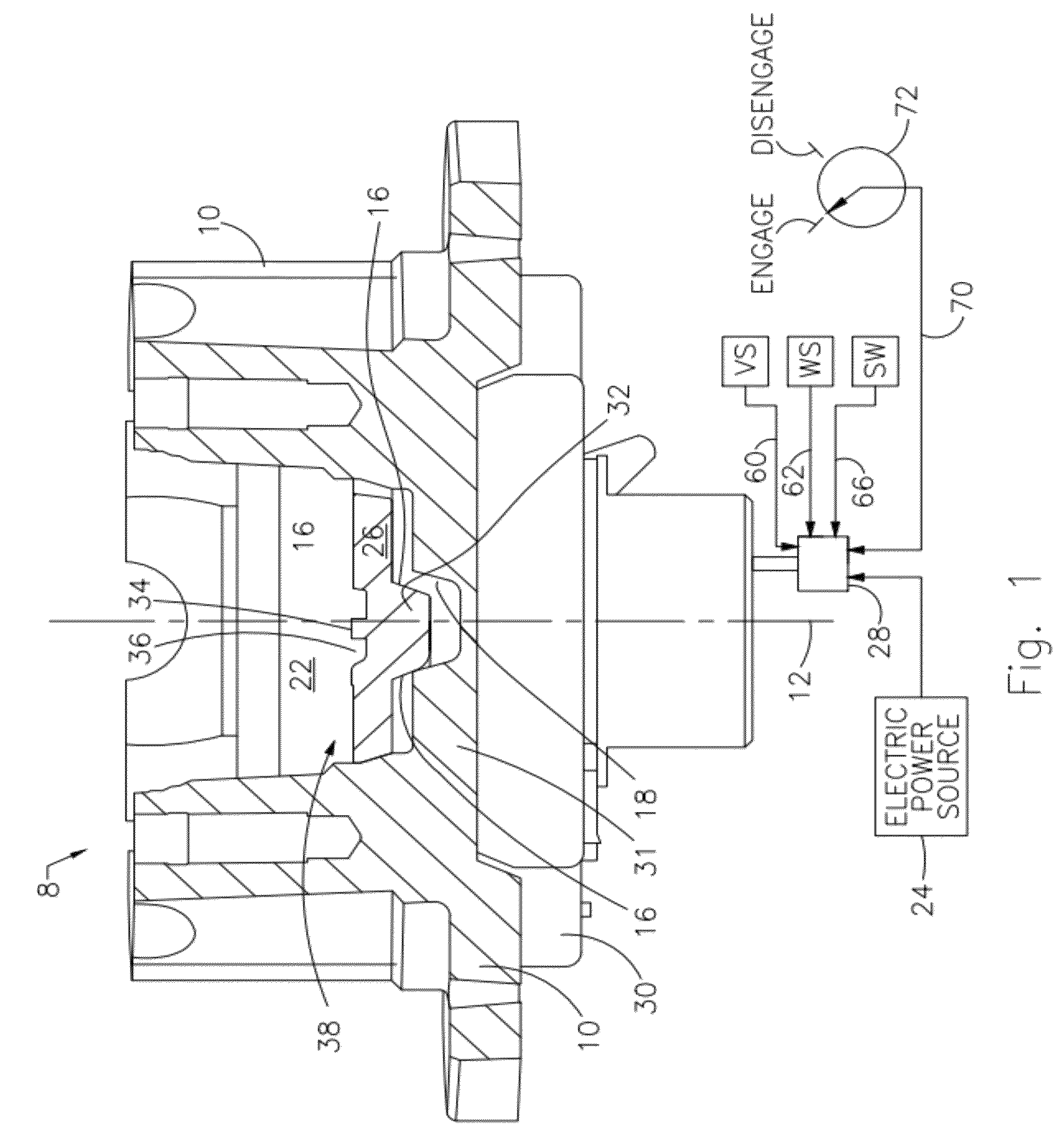
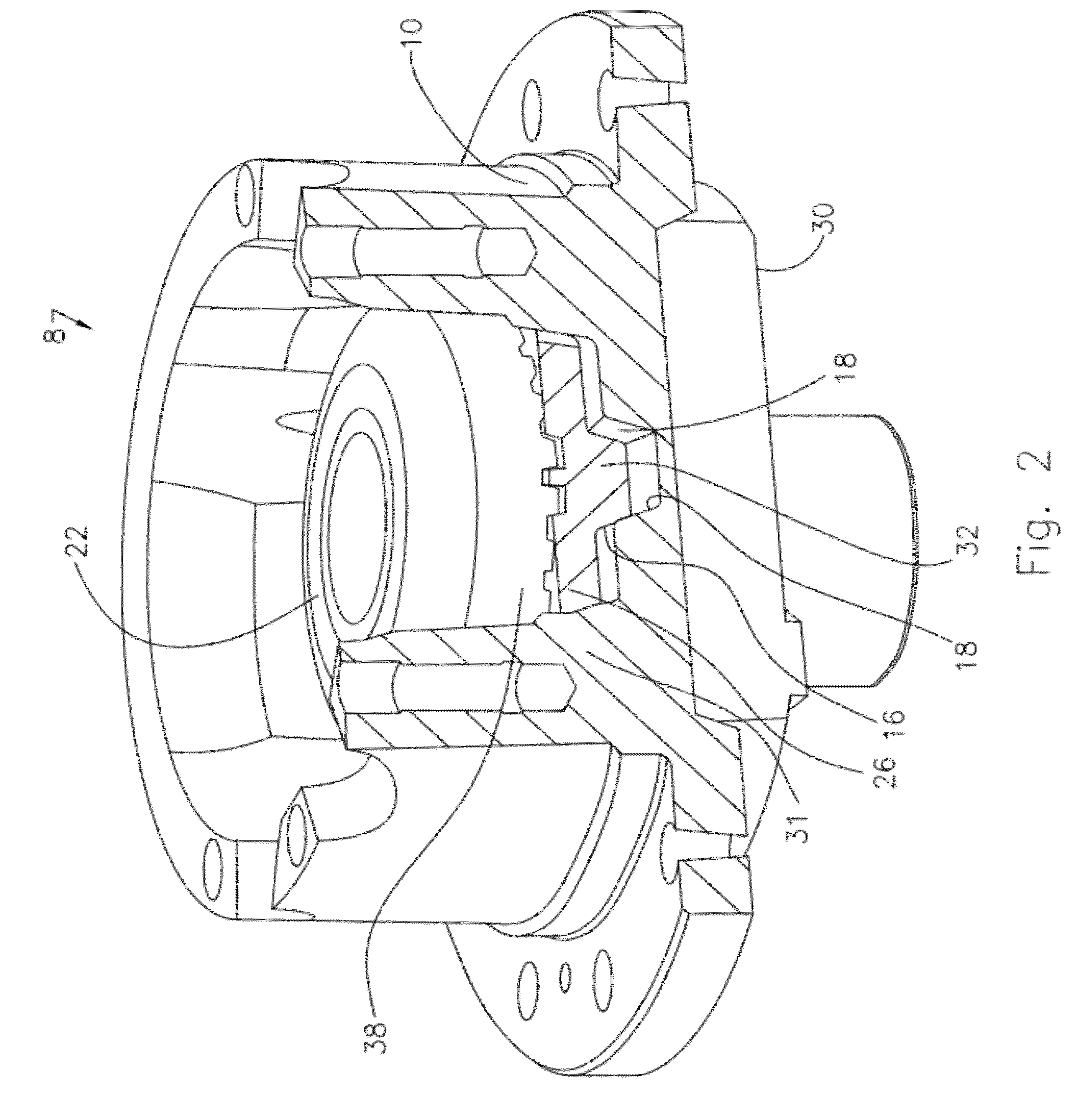
[0019]Referring to FIGS. 1-3, an electronically controlled differential mechanism 8 includes a differential case 10 arranged concentrically about an axis 12; ramps 16, 18; side gear 22; electric power source 24, locking ring 26, electronic controller 28, and electromagnetic coil 30. Ramps 16, formed on the locking ring, and ramps 18, formed on the differential case 10, are angularly spaced at three or four locations about axis 12 such that each of the ramps 16 is aligned angularly with one of the ramps 18.

[0020]Locking ring 26 is formed with angularly spaced posts 27, each post extending axially through a hole in a web 31 formed in case 10, thereby continually engaging the case 10 and the locking ring 26 for rotation as a unit, but permitting the ring to move axially independently of the case.

[0021]Locking ring 26 is formed also with angularly spaced legs 32, each leg 32 being formed with two ramps 16, and clutch teeth 34. Similarly, side gear 22 is formed with clutch teeth 36. The ...


PUM


Abstract

A method for controlling a clutch of an electronic locking differential for a vehicle includes determining either that a speed of the vehicle is less than a reference speed or that a desired state of the clutch is a disengaged state, determining that an angular displacement of a steering wheel from a centered position is less than a first reference angle, and disengaging the clutch.

Description

BACKGROUND OF THE INVENTION[0001]1. Field of the Invention[0002]The invention relates generally to a differential mechanism, which transmits rotating power to the wheels of a motor vehicle.[0003]2. Description of the Prior Art[0004]A locker clutch can be used in a differential mechanism to secure one of the side gears and its axle shaft against rotation relative to the differential carrier, thereby enhancing traction of the driven wheels that are supplied with power through the differential.[0005]When actuated, an electronic locking differential (ELD) mechanically connects a side gear to the differential case using an electrically-controlled lock mechanism, typically a dog clutch.[0006]When the clutch is engaged, the electronic locking differential prevents relative speed differentials across the controlled wheels and transmits full engine combustion torque amplified by the transmission and axles torque ratios and reduced by efficiency and rotational losses, to the controlled wheels...

Claims


Application Information

Patent Timeline
Patent Type & Authority Patents(United States)
IPC IPC(8): G06F7/00
CPCB60K23/04F16H48/30F16H2048/205F16H48/24
Inventor POVIRK, JACOB M.SAIEG, JOHN R.PIETRZYK, GARY M.
Owner FORD GLOBAL TECH LLC
Why Eureka
Try Eureka