
Hearing aid with an attenuation element

a technology of attenuation element and hearing aid, which is applied in the field of hearing aids, can solve the problems of generating parasitic solid-borne sound feedback in the hearing device, and generally being perceived as an extremely unpleasant whistling sound, so as to increase the attenuation effect, and reduce the overall volume of the hearing aid

Active Publication Date: 2012-09-04
SIVANTOS PTE LTD
View PDF10 Cites 13 Cited by
  • Summary
  • Abstract
  • Description
  • Claims
  • Application Information

AI Technical Summary

Benefits of technology

[0008]In order to reduce the risk of feedbacks and / or to reduce the transmission of mechanical oscillations from the receiver to the microphone via the hearing aid structure, receivers are positioned as far as possible from the microphones. This allows vibrations from the receiver at the site of the microphone to have already died out. One further measures consists in receivers being mounted in elastic supports, mostly soft rubber retainers, which are to prevent a solid-borne sound transmission from the receiver to the hearing aid housing. In addition, microphones are already mounted in such supports in order to prevent solid-borne sound from transferring from the hearing aid housing to the microphone housing.
[0032]Instead, it is however also possible to dispense with reductions in the hearing aid volume and instead use the increased attenuation effect and operate the receiver at high power, without feedbacks occurring.

Problems solved by technology

In addition to useful sound, miniaturized electromagnetic receivers for hearing devices also generate parasitic solid-borne sound.
Since the microphone signal in the hearing aid is routed again to the receiver as an amplified signal, there is a very high risk that solid-borne sound bridges may result in feedbacks in the hearing device.
Feedbacks are generally perceived as an extremely unpleasant whistling sound, which is exceedingly irksome for the hearing aid wearer.
The elastic supports take up considerable space, particularly if a very effective solid-borne sound insulation is to be achieved.
By contrast, with a compact, small design, they are mostly only inadequate.

Method used


Image

  • Hearing aid with an attenuation element
  • Hearing aid with an attenuation element
  • Hearing aid with an attenuation element

Examples


Embodiment Construction

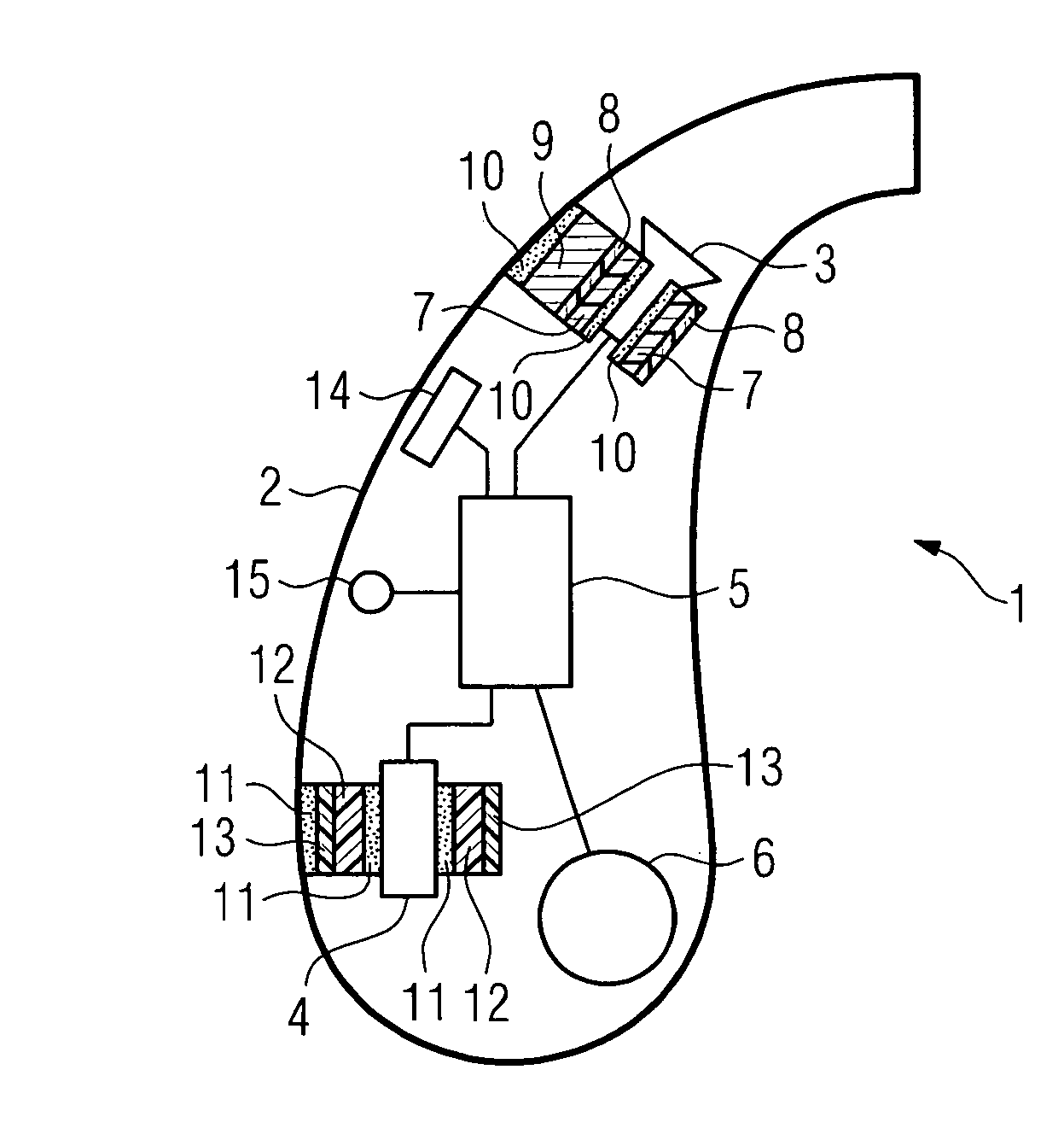
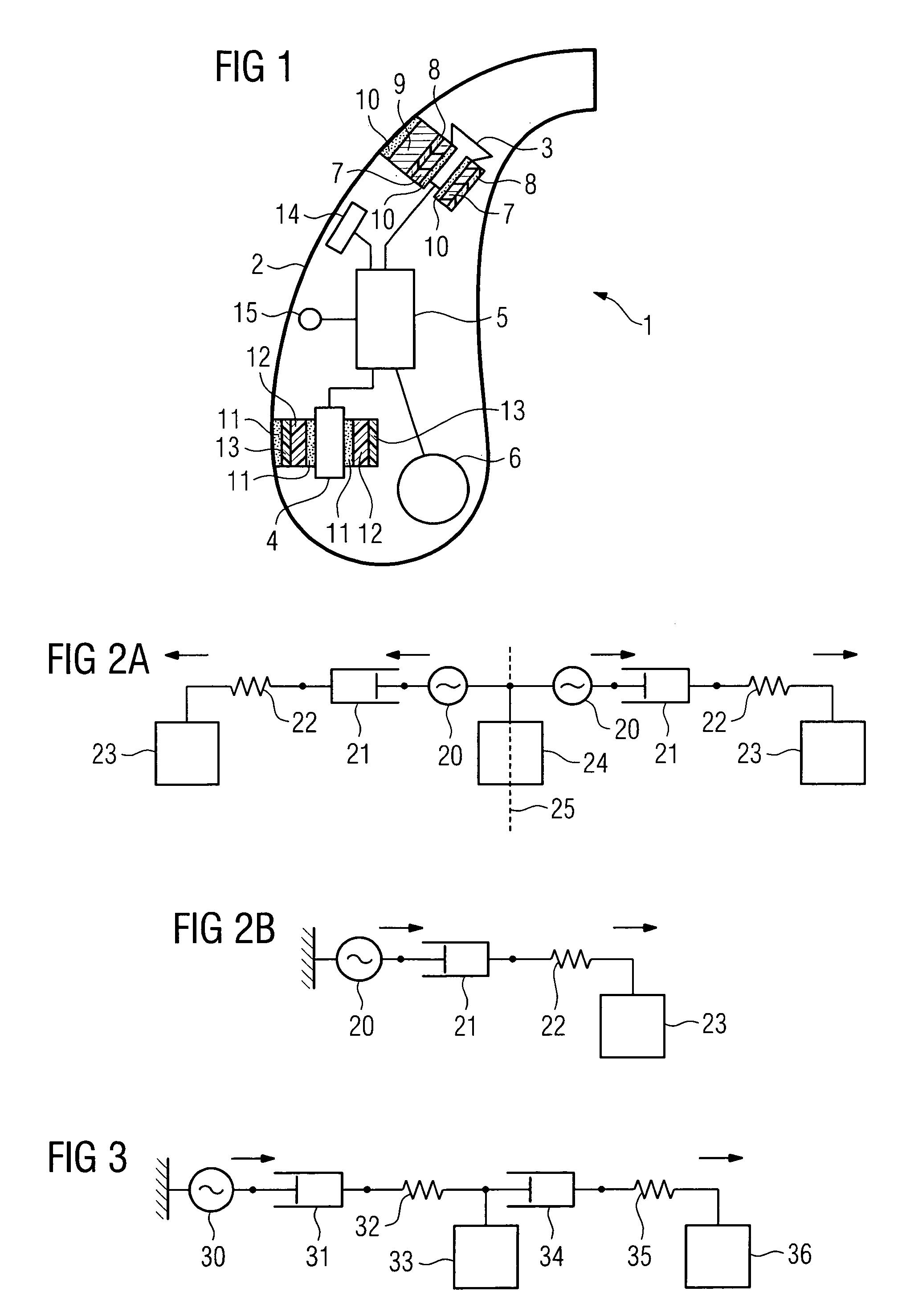
[0043]FIG. 1 shows a schematic representation of a hearing aid 1 with an attenuation element. A patented housing 2 of the hearing aid 1 is shown, in which the essential electronic components, which belong to the signal processing electronic system, are shown.

[0044]These electronic components include a receiver 3, which generates acoustic signals, which are to be fed to an ear of the hearing aid wearer. The receiver 3 is connected to a signal processing facility 5, the essential object of which is the processing of recorded acoustic signals and the amplification thereof. It is connected to a microphone 4, which is used to receive acoustic signals. Its power supply supplies the signal processing facility 5 from a battery 6.

[0045]Further electronic components, e.g. a telecoil 14 for receiving telephone receiver signals, or a wireless coil 15, are likewise provided in the housing. Furthermore, further components (not shown), e.g. a Bluetooth antenna for receiving data communication sign...


PUM


Abstract

A shielding element and a decoupling element are integrated into a combined attenuation element. The shielding element may be a shielding foil, preferably made of copper. The attenuation element may include a flexible backing foil, preferably a plastic backing foil which supports the shielding foil. It may also include an adhesive layer with which the electronic component is affixed to a housing. The physical properties of all elements of the attenuation element are attuned to one another such that it simultaneously attenuates both electromagnetic alternating fields as well as mechanical oscillations.

Description

CROSS REFERENCE TO RELATED APPLICATIONS[0001]This application claims priority of German application No. 20 2008 011 759.3 DE filed Sep. 3, 2008, and German application No. 10 2008 045 668.3 which are both incorporated by reference herein in their entirety.FIELD OF INVENTION[0002]The invention relates to a hearing aid as well as an electronic component for generating or processing electromagnetic alternating fields and sound waves for a hearing aid with a shielding element for attenuating electromagnetic alternating fields and a decoupling element for attenuating mechanical oscillations. The invention also relates to a method for dimensioning the individual components, which are provided to attenuate electromagnetic alternating fields and mechanical oscillations.BACKGROUND OF INVENTION[0003]Hearing aids are used to supply hearing-impaired persons with suitable auditory signals. The auditory signals generally consist of acoustic signals, which are recorded by the hearing aid, pass thr...

Claims


Application Information

Patent Timeline
Patent Type & Authority Patents(United States)
IPC IPC(8): H04R25/00
CPCH04R25/456H04R25/604H04R2225/49
Inventor BALLY, UWENIKLES, PETERRADICK, ERIKASCHATZLE, ULRICH
Owner SIVANTOS PTE LTD
Learn More