Guidewire exchange systems to treat spinal stenosis

a technology of spinal stenosis and guidewires, applied in the field of medical/surgical devices and methods, can solve the problems of many challenges, reduced or even no direct visualization, and the development of less invasive surgical methods and devices

Active Publication Date: 2012-09-04
SPINAL ELEMENTS INC +1
View PDF714 Cites 1207 Cited by
  • Summary
  • Abstract
  • Description
  • Claims
  • Application Information

AI Technical Summary

Problems solved by technology

Developing less invasive surgical methods and devices, however, can pose many challenges.
For example, some challenges of less invasive techniques include working in a smaller operating field, working with smaller devices, and trying to operate with reduced or even no direct visualization of the structure (or structures) being treated.
These challenges are compounded by the fact that target tissues to be modified often reside very close to one or more vital, non-target tissues, which the surgeon hopes not to damage.
One of the initial obstacles in any given minimally invasive procedure, therefore, is positioning a minimally invasive surgical device in a desired location within the patient to perform the procedure on one or more target tissues, while avoiding damage to nearby non-target tissues.
In a patient, this may manifest as pain, impaired sensation and / or loss of strength or mobility.
Epidural steroid injections may also be utilized, but they do not provide long lasting benefits.
When these approaches are inadequate, current treatment for spinal stenosis is generally limited to invasive surgical procedures to remove ligament, cartilage, bone spurs, synovial cysts, cartilage, and bone to provide increased room for neural and neurovascular tissue.
Removal of vertebral bone, as occurs in laminectomy and facetectomy, often leaves the affected area of the spine very unstable, leading to a need for an additional highly invasive fusion procedure that puts extra demands on the patient's vertebrae and limits the patient's ability to move.
Unfortunately, a surgical spine fusion results in a loss of ability to move the fused section of the back, diminishing the patient's range of motion and causing stress on the discs and facet joints of adjacent vertebral segments.
Such stress on adjacent vertebrae often leads to further dysfunction of the spine, back pain, lower leg weakness or pain, and / or other symptoms.
Furthermore, using current surgical techniques, gaining sufficient access to the spine to perform a laminectomy, facetectomy and spinal fusion requires dissecting through a wide incision on the back and typically causes extensive muscle damage, leading to significant post-operative pain and lengthy rehabilitation.
Thus, while laminectomy, facetectomy, discectomy, and spinal fusion frequently improve symptoms of neural and neurovascular impingement in the short term, these procedures are highly invasive, diminish spinal function, drastically disrupt normal anatomy, and increase long-term morbidity above levels seen in untreated patients.
Although a number of less invasive techniques and devices for spinal stenosis surgery have been developed, these techniques still typically require removal of significant amounts of vertebral bone and, thus, typically require spinal fusion.

Method used


Image

  • Guidewire exchange systems to treat spinal stenosis
  • Guidewire exchange systems to treat spinal stenosis
  • Guidewire exchange systems to treat spinal stenosis

Examples


Embodiment Construction

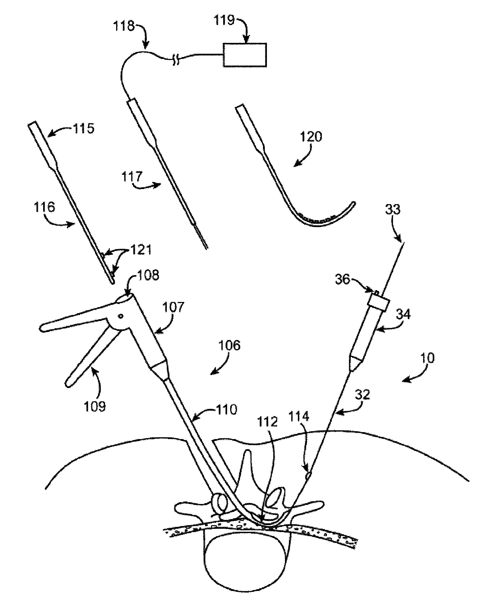
[0087]In general, the guidewire systems described herein includes a guidewire and at least one surgical device that are configured so that the proximal end of the guidewire couples to the distal end of the guidewire. The guidewire typically has a distal end that is configured to extend from a subject's body and be manipulated, and a proximal end that includes a coupling member for coupling to the surgical device. The coupling member may be referred to as a device coupling member and may be located at or near the proximal end of the guidewire. Any appropriate surgical device or devices may be included as part of the guidewire system. The surgical device typically includes a coupling member on or near its distal end that is configured to mate with the coupling member on or near the proximal end of the guidewire. The device-side coupling member may be referred to as a guidewire coupling member.

[0088]Methods of using these systems, and particularly methods of quickly exchanging surgical...


PUM


Abstract

Guidewire exchange systems, devices and methods, for positioning and actuating surgical devices in a desired position between two tissues in a patient's body are described. A guidewire may be coupled to a surgical device for positioning and actuating (e.g., urging against a target tissue). The guidewire may be exchanged between different surgical devices during the same procedure, and the guidewire and surgical devices may be releaseably or permanently coupled. The surgical device generally includes one or more guidewire coupling members. A system may include a guidewire and a surgical device having a guidewire coupling member. Methods, devices and systems may be used in open, less-invasive or percutaneous surgical procedures.

Description

CROSS-REFERENCE TO RELATED APPLICATIONS[0001]This application is claims the benefit as a continuation-in-part of pending U.S. patent application Ser. No. 11 / 251,199, filed on Oct. 15, 2005, titled “Devices and Methods for Tissue Modification”; which claims the benefit of U.S. Provisional Patent Application Ser. No. 60 / 685,190, filed on May 27, 2005, titled “Methods and Apparatus for Selective Surgical Removal of Tissue”; U.S. Provisional Patent Application Ser. No. 60 / 681,719, filed May 16, 2005, titled “Methods and Apparatus for Selective Surgical Removal of Tissue”; U.S. Provisional Patent Application Ser. No. 60 / 681,864, filed May 16, 2005, titled “Methods and Apparatus for Selective Surgical Removal of Tissue”; U.S. Provisional Patent Application Ser. No. 60 / 622,865, filed Oct. 28, 2004, titled “Methods and Apparatus for Selective Surgical Removal of Tissue”; and U.S. Provisional Patent Application Ser. No. 60 / 619,306, filed Oct. 15, 2004, titled “Methods and Apparatus for the T...

Claims


Application Information

Patent Timeline
Patent Type & Authority Patents(United States)
IPC IPC(8): A61B17/00
CPCA61B17/1671A61B17/29A61B17/320016A61B17/32002A61B17/32053A61B17/320758A61B17/3401A61B17/3403A61B17/3421A61B17/3496A61B18/1487A61B19/40A61M25/09041A61M25/0905A61N1/08A61B17/320708A61B18/1477A61B2017/00261A61B2017/00287A61B2017/003A61B2017/00349A61B2017/00469A61B2017/00477A61B2017/00867A61B2017/320004A61B2017/320044A61B2017/32006A61B2018/1407A61B2018/1425A61B2019/461A61B2019/481A61N1/0551A61N2001/0578A61B90/04A61B2090/061A61B2090/08021
Inventor BLEICH, JEFFREY L.SCHMITZ, GREGORY P.LEGUIDLEGUID, ROYBLEAM, JEFFEREY
Owner SPINAL ELEMENTS INC
Why Eureka
Try Eureka