
Hair holder, open/close device for hair-holding member, and hair holder for hair treatment

a technology for hair holder and hair bundle, which is applied in the direction of hair cleaning, hair equipment, travelling articles, etc., can solve the problems of hair holder hair holder disclosed in patent document 2 being prone to fall off during hair treatment operations, and hair holder being easily fixed. , to achieve the effect of easy and quick hair holder insertion, and increasing the manufacturing cost of the tub

Inactive Publication Date: 2012-09-04
KAO CORP
View PDF18 Cites 13 Cited by
  • Summary
  • Abstract
  • Description
  • Claims
  • Application Information

AI Technical Summary

Benefits of technology

The present invention provides a hair holder for hair treatment that allows easy and quick hair-bundle insertion into a tube and fixing of the tube to the hair bundle. The hair holder is designed to overcome the drawbacks of conventional art, such as falling off during hair treatment operations and causing pain to the user. The invention achieves these technical effects by integrating a clip-type fixing member with a tube and allowing for easy attachment and stable attachment to the head. The hair holder also includes an open / close device for the hair-holding member that allows for easy opening and closing of the tube.

Problems solved by technology

However, merely fixing the hair holder to the hair bundle inside the tube may cause the tube to fall off from its initially-fixed position on the hair bundle during hair treatment operations.
For example, the hair holder is prone to fall off in cases where the roll-up means does not sufficiently roll up the hair bundle.
The hair holder disclosed in Patent Document 2 is also prone to fall off from the hair bundle during hair treatment operations.
The clip-type fixing member, however, does not have the function of opening up the opening of the tube.
The sealing means of Patent Document 3, however, increases the manufacturing cost of the tube as well as the hair holder.

Method used


Image

  • Hair holder, open/close device for hair-holding member, and hair holder for hair treatment
  • Hair holder, open/close device for hair-holding member, and hair holder for hair treatment
  • Hair holder, open/close device for hair-holding member, and hair holder for hair treatment

Examples


examples

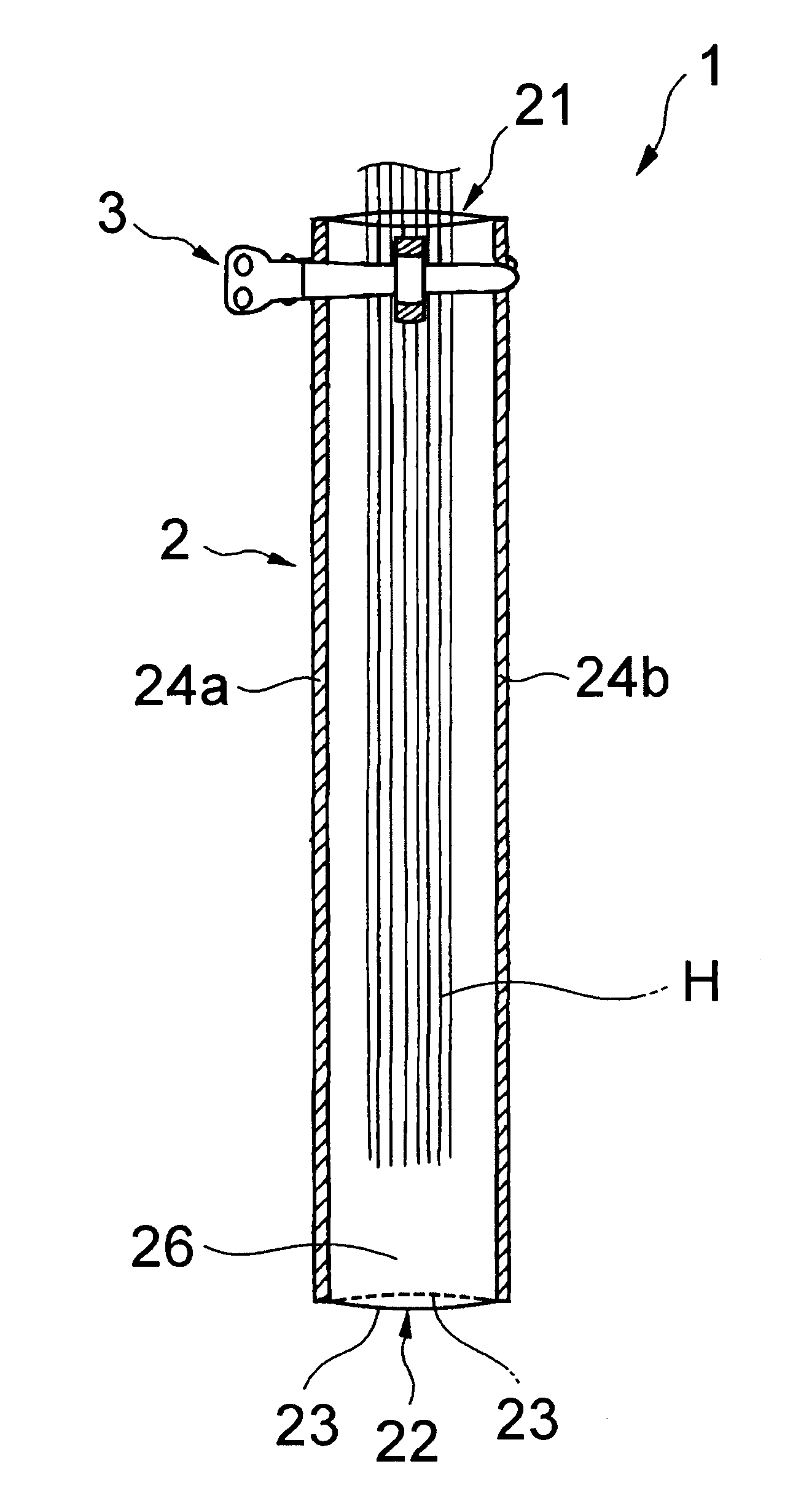
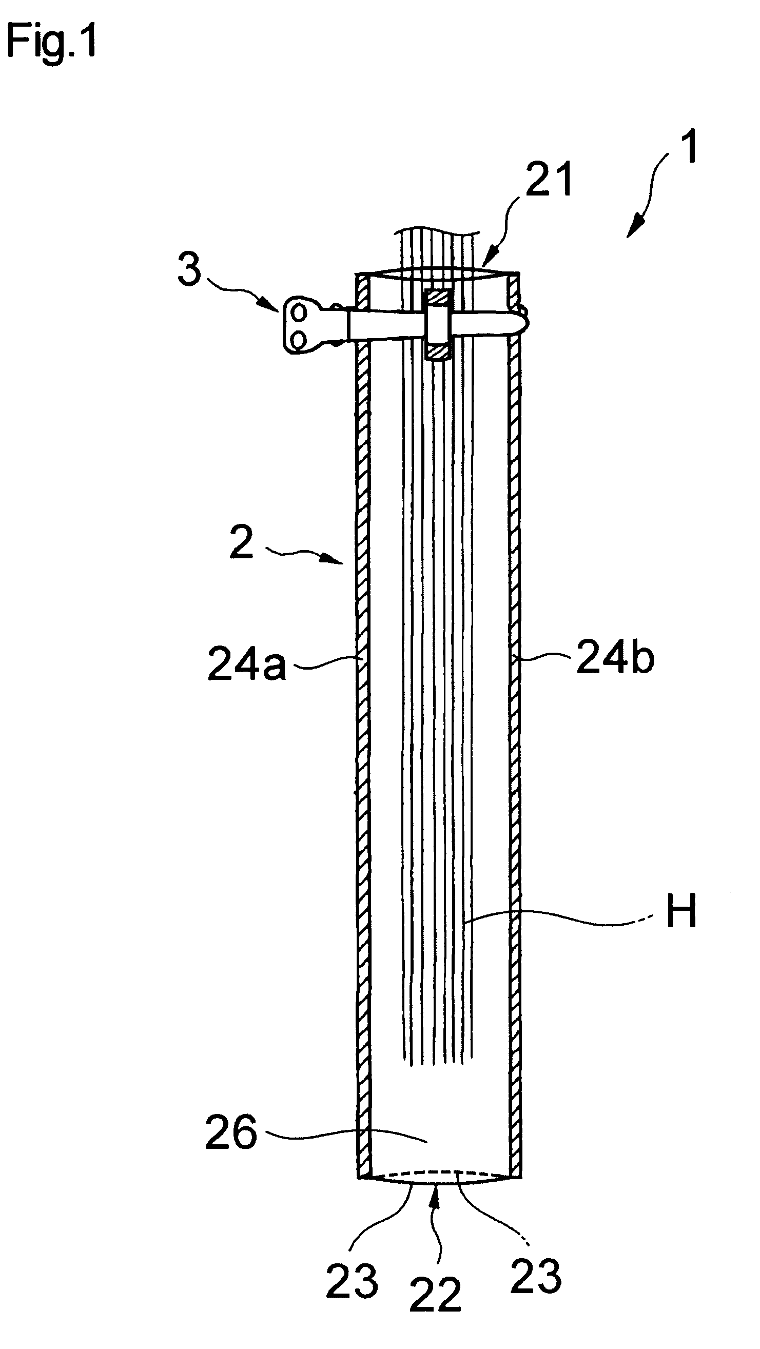
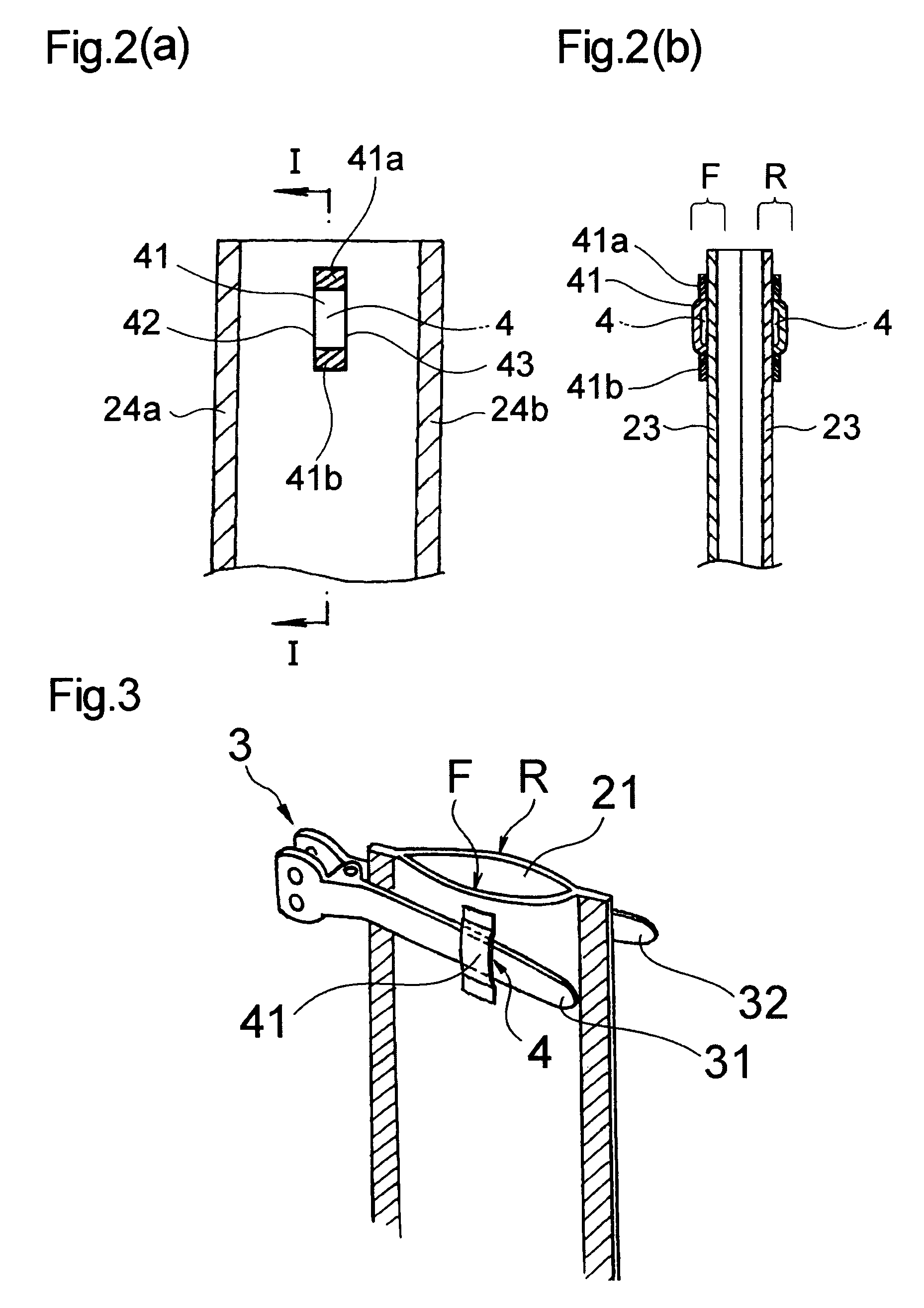
[0215]A hair holder having the configuration shown in FIGS. 1 to 3 was prepared. Passages 4 were provided respectively on the opposing first and second sides F and R of the tube 2, with the width of the passage (equal to the width of the strip for forming the passage; referred to as “passage strip” in Table 1) being set as shown in Table 1. The strip for forming the passage was arranged so that the center of the width of the strip is positioned in the center between the one side edge 24a and the other side edge 24b of the tube.

[0216]A clip-type fixing member having the configuration shown in FIG. 4 was mounted to each hair holder prepared. The opening 21 was opened up to measure the maximum opening amount (see FIG. 4(b)). Also, using a haired head model, the ease of inserting hair into each hair holder was evaluated. The evaluation criteria and the results are shown in Table 1.

[0217]

TABLE 1Width W of Tube between Both Side Ends (Bag Width) = 50 mmComparativeExamplesExampleWidth of P...


PUM


Abstract

A hair holder includes a tube formed of a sheet in such a design as to allow a hair bundle to be inserted from a one-end opening at one end of the tube toward an other-end opening at the other end thereof. The tube includes an integration mechanism in the vicinity of the one-end opening. The integration mechanism is for a clip-type fixing member having a pair of pinchers. The one-end opening is openable and closable by operating the clip-type fixing member having been integrated with the tube.

Description

TECHNICAL FIELD[0001]The present invention relates to a hair holder capable, for example, of dyeing or permanent-waving a prescribed amount of hair.[0002]The present invention also relates to an open / close device for opening and closing a tubular hair-holding member that holds a hair bundle inserted therein and that is used in applying treatments to the hair, such as partial coloring and partial permanent-waving, and to a hair holder for hair treatment having the open / close device fixed to the hair-holding member.BACKGROUND ART[0003]Hair holders formed of a tube and capable of, for example, dyeing or permanent-waving a prescribed amount of hair are conventionally known. These types of hair holders are formed of a flexible tube and are so designed that a hair bundle is inserted into the tube from one end thereof. For example, in dyeing a hair bundle, a dyeing agent is supplied into the tube and is applied inside the tube to the hair bundle.[0004]Using a material that is impermeable t...

Claims


Application Information

Patent Timeline
Patent Type & Authority Patents(United States)
IPC IPC(8): A45D19/18A45D2/00
CPCA45D2/122A45D8/24A45D19/0008A45D2019/0091A45D19/012A45D19/0066
Inventor TOJO, TAKEHIKOSAITO, KOJIKOBAYASHI, HIDEOWATANABE, TOSHIOENOMOTO, HARUOMI
Owner KAO CORP
Learn More