Solar-shading assembly with hidden fastening device

a technology of fastening device and solar panel, which is applied in the direction of sunshades, building components, extraordinary structures, etc., can solve the problems of increasing manufacturing and customer costs, bulky prior art arrangements, and reasonable complexity

Active Publication Date: 2012-09-04
LEVOLUX A T
View PDF17 Cites 2 Cited by
  • Summary
  • Abstract
  • Description
  • Claims
  • Application Information

AI Technical Summary

Problems solved by technology

The prior art arrangements are also bulky and reasonably complex, leading to increased manufacturing and customer costs.

Method used


Image

  • Solar-shading assembly with hidden fastening device
  • Solar-shading assembly with hidden fastening device
  • Solar-shading assembly with hidden fastening device

Examples


Embodiment Construction

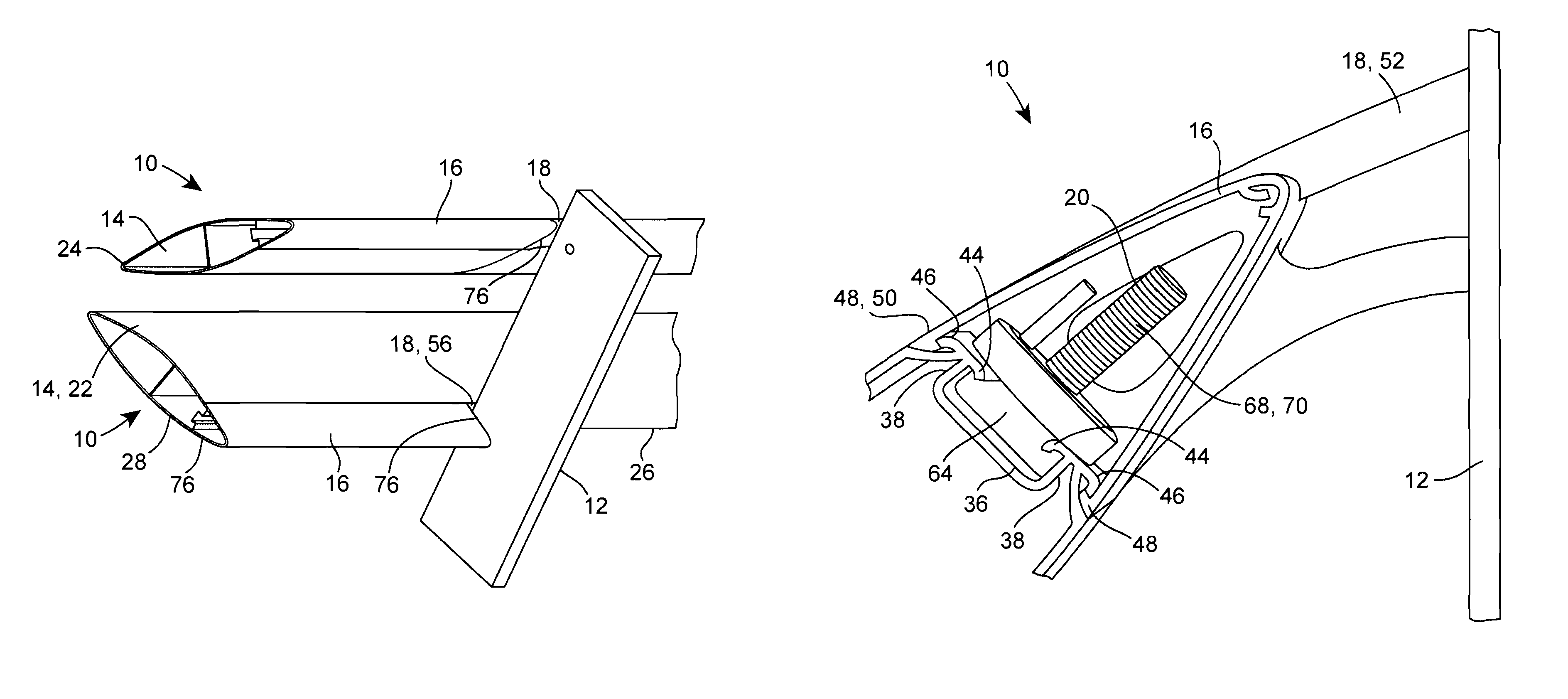
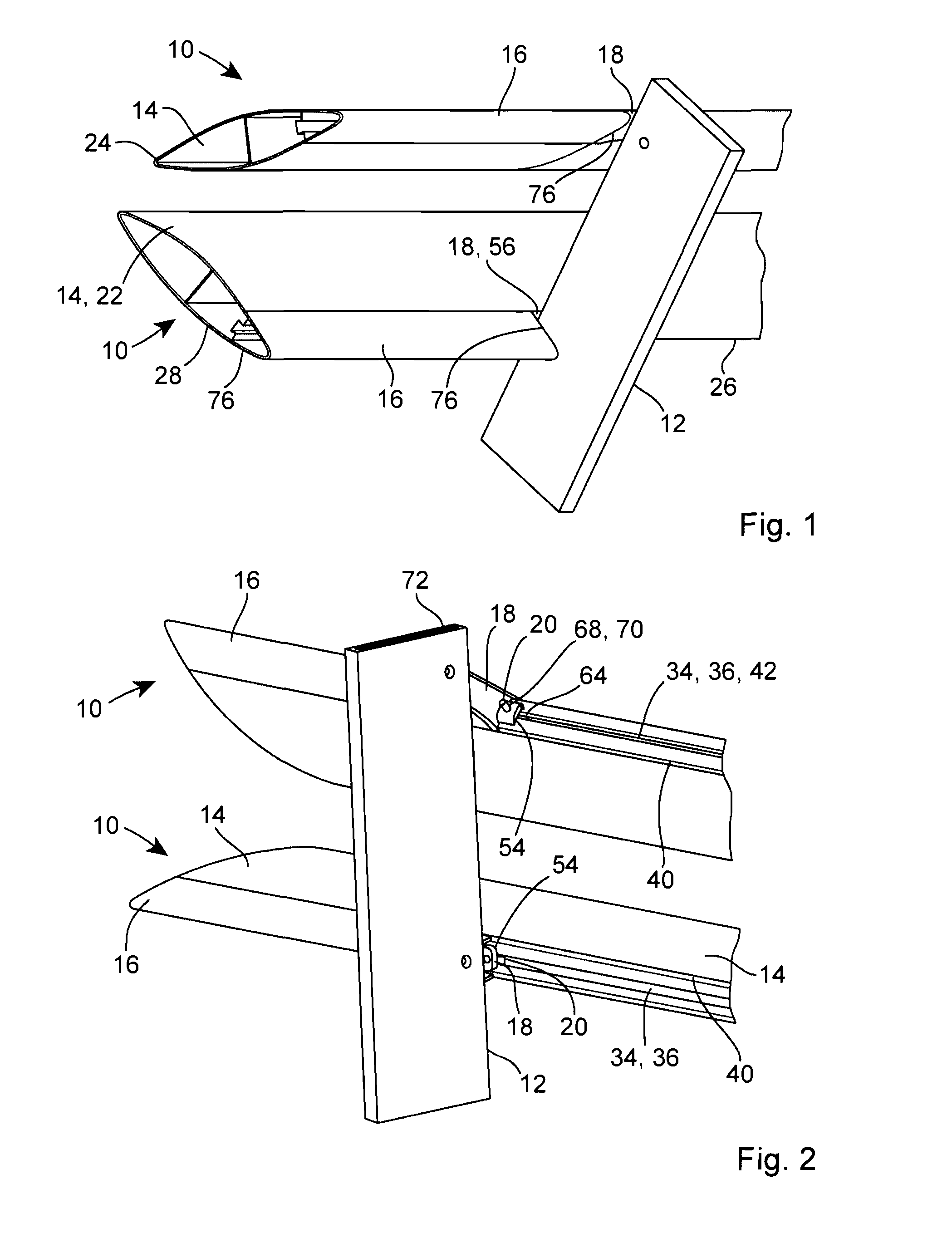
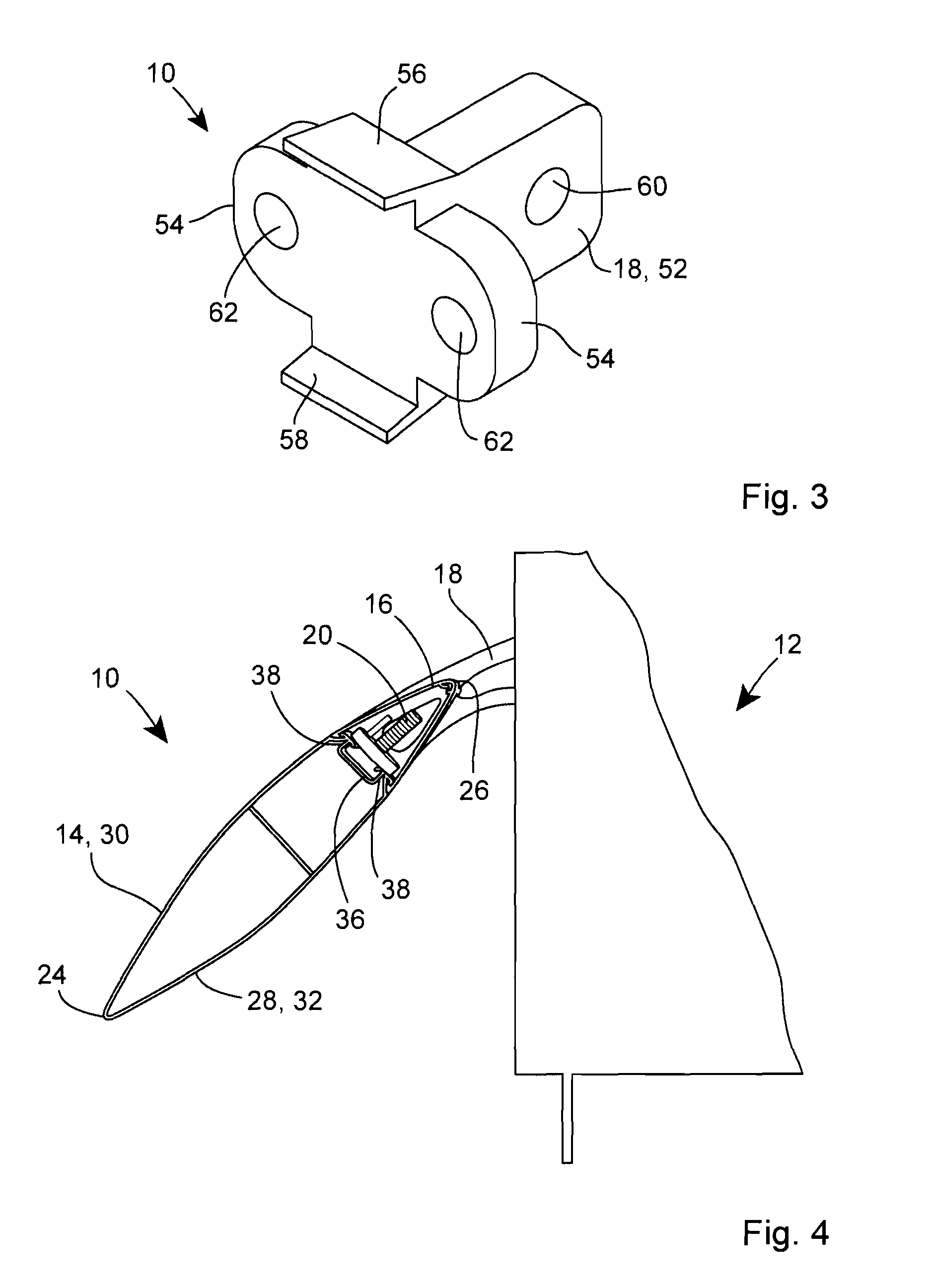
[0015]Referring firstly to FIGS. 1 to 3 of the drawings, there is shown a first embodiment of a solar-shading assembly 10 and a support mullion 12, typically fixed to project externally of a building. The solar-shading assembly 10 includes an elongate louver member 14, an elongate cap element 16, a bracket 18 for attachment to the support mullion 12, and a fastening device 20 for fastening the bracket 18 to the louver member14.

[0016]The louver member 14, in this case, is one-piece and may be, for example, an extrusion from plastics or metal. Alternatively, the louver member 14 may be two-pieces, for example, an upper part and a lower part, connected together via snap-fitting and / or one or more screw-threaded fasteners.

[0017]The louver member 14 has an elongate body 22 with longitudinal parallel front and rear edges 24, 26, lateral end sides 28 which, if free, are typically capped, and upper and lower surfaces 30, 32 which span between the front and rear edges 24, 26 and end sides 28...


PUM


Abstract

A solar-shading assembly for fastening to a support mullion, comprises an elongate louver member having longitudinal front and rear edges, an elongate cap element for extending along and covering the rear edge, a bracket which is connectable to the support mullion, and a fastening device for connecting the bracket to the rear edge of the louver member. The in use fastening device is coverable by the cap element so as to hide the fastening device from view. Preferably, at least part of the bracket is also coverable by the cap element so as to hide the said part of the bracket from view.

Description

[0001]The present invention relates to a solar-shading assembly for fastening to a support mullion, the assembly having a hidden fastening device.BACKGROUND OF THE INVENTION[0002]Solar-shading is known, and is frequently used on the exterior of a building to prevent or limit directly incident solar energy on windows. Louvers are known which are supported at their lateral ends, and which can also be supported along their edge lengths.[0003]However, in all cases, the brackets and fastenings are fully visible. From an aesthetic point of view, architects prefer to have as few of the fixings and fasteners on view as possible. When a louver is held at the longitudinal edge, the rotational load is such that bracket locations must necessarily be very close to prevent catastrophic mechanical failure.[0004]The prior art arrangements are also bulky and reasonably complex, leading to increased manufacturing and customer costs.[0005]The present invention seeks to provide a solution to these prob...

Claims


Application Information

Patent Timeline
Patent Type & Authority Patents(United States)
IPC IPC(8): E06B7/08
CPCE06B7/082E04F10/08E06B7/02E06B9/386F24F13/08
Inventor BRAYBROOK, PETER
Owner LEVOLUX A T
Why Eureka
Try Eureka