Strict-sense minimal spanning switch non-blocking architecture

a minimal spanning switch and non-blocking technology, applied in data switching networks, multiplex communication, digital transmission, etc., can solve problems such as undesirable re-routing of signals, dropped telephone connections, and interrupted or blocked connections, so as to minimize the amount of logic duplicated on each data stream, the effect of maximizing efficiency

Active Publication Date: 2012-08-28
INTEL CORP
View PDF20 Cites 4 Cited by
  • Summary
  • Abstract
  • Description
  • Claims
  • Application Information

AI Technical Summary

Benefits of technology

[0012]The present invention discloses a novel Strict-Sense Minimal Spanning Non-Blocking Architecture for use in frame-based data communications networks, providing the ability to re-route a telecommunications connection without interrupting the data signal. To maximize efficiency, the amount of logic duplicated on each data stream is minimized through the use of a n framer system, where n=the total number of framers in the system. In addition, n=the total number of data input signals which are transmitted into the crossbar connections (r) of the system. In the present invention, a “framer” refers to a machine which recognizes inherent framing patterns in transmitted data which occurs at predictable intervals. In the n framer system, each of the n bit streams enters n framers at a crossbar connection, and the n framers subsequently determine the inherent framing patterns within the transmitted data which are necessary for re-alignment. From these inherent framing patterns, the n framers can derive an arbitrary frame start signal, or the “start of frame.” The start of frame, as derived by the n framers, indicates to the n framers to write the transmitted data into a specific, but arbitrary location(s) of n buffers. These arbitrary locations of n buffers represent the offsetting bit location in each of the n buffers where the n framers are to start writing the transmitted data to allow the data to be written into the n buffers in a re-aligned fashion. A multiplexer can then read out the realigned data from the n buffers and select from any of the re-aligned data signals to provide a single data output signal. In an illustrative embodiment of the invention, the n incoming data input signals are transmitted to n framers, where each of the n incoming data input signals are divided into d data signals, where d can be any arbitrary and user-definable amount of data signals. This provides a total of x internal data signals, as n×d=x. The x internal data signals are then written into a specific, but arbitrary location(s) of x buffers. A multiplexer can then read out the realigned data from the x buffers and select one, single data output signal; i.e., each crossbar connection has one data output signal, therefore m crossbar connections have m data output signals. Through this method, each crossbar connection of the switch will output the exact same data in each of the m data output signals. Therefore, when any of m crossbar connections (where m=the total number of data output signals switches from one sub-switch to another sub-switch, no interruption occurs; as the data on each sub-switch within a crossbar connection is identical, any connection can be successfully used by the switch.

Problems solved by technology

However, as (2n−2) crossbar connections may be unable to provide every necessary connection, an extra crossbar is provided to ensure Strict-Sense Non-Blocking, with (2n−1) middle stage crossbar connections.
When implementing a Clos Network which does not adhere to m≧(2n−1), the data connections may need to be re-routed in order to establish new connections, and such re-routing would result in interrupted or blocked connections, i.e., dropped telephone connections.
Such re-routing of signals is undesirable; the signals being transmitted are already carrying data, thus re-routing the data signal would again result in interrupted or blocked connections, i.e., dropped telephone connections.

Method used


Image

  • Strict-sense minimal spanning switch non-blocking architecture
  • Strict-sense minimal spanning switch non-blocking architecture
  • Strict-sense minimal spanning switch non-blocking architecture

Examples


Embodiment Construction

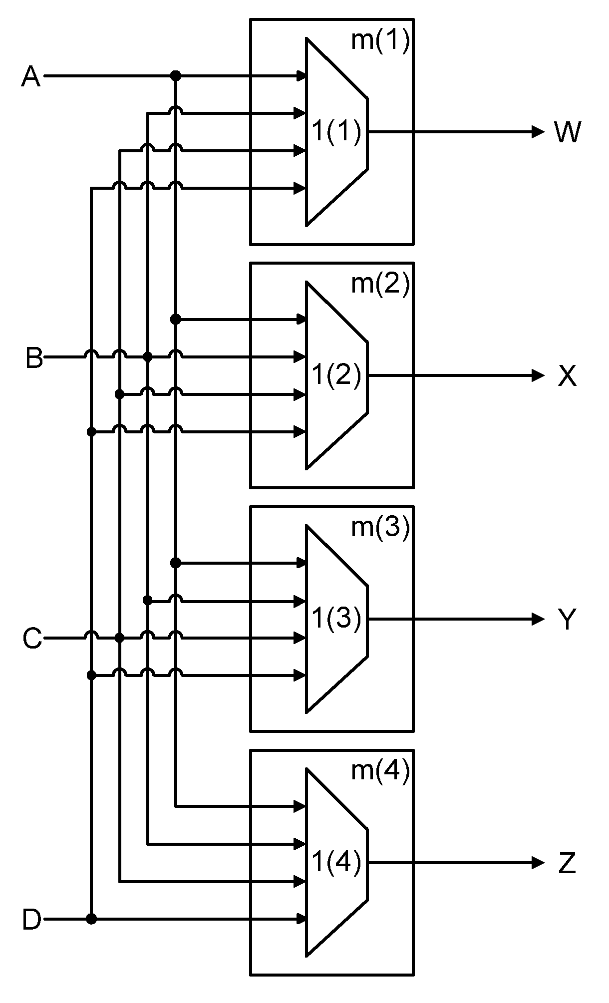
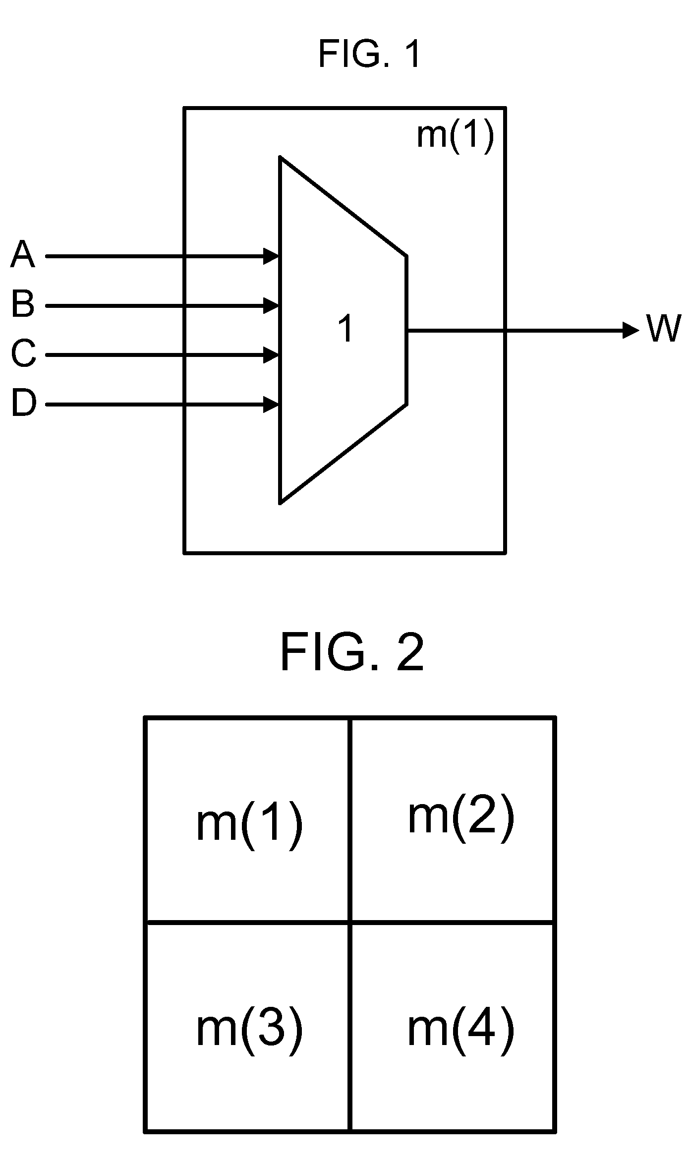
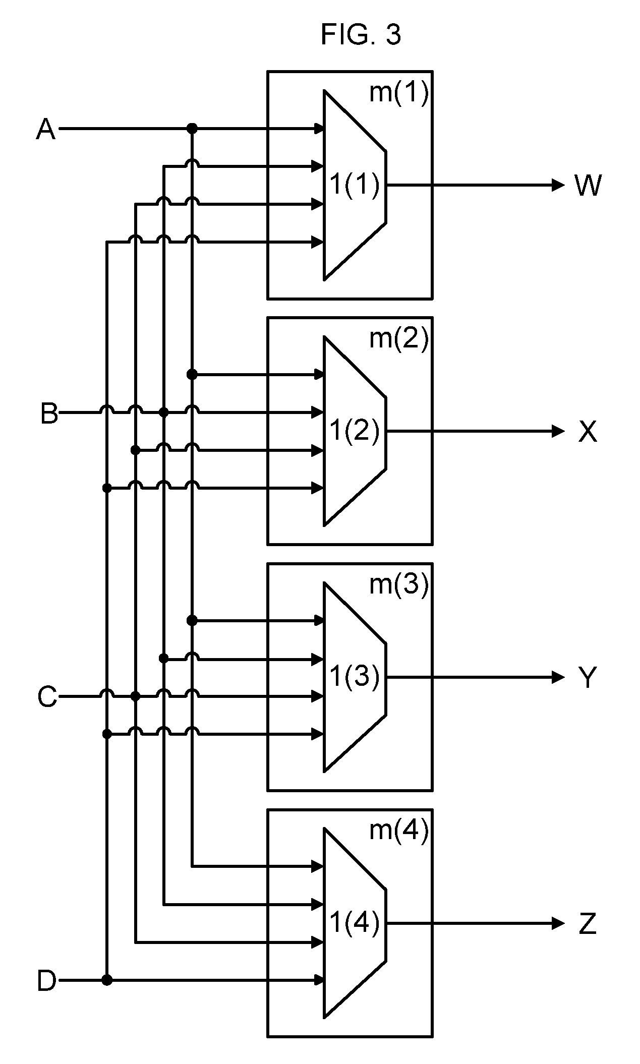
[0020]An illustrative embodiment of the invention employs a n framer system as applied to a 4×4 switch. The crossbar connections employed may be Field Programmable Gate Arrays (FPGAs) or any other logic circuitry element. It should be noted that this example is provided for illustrative purposes only and is not meant to limit the scope of the invention, as any size switch can be accommodated. In the 4×4 switch, each of the crossbar connections m has four separate data input locations and one single data output location. This is illustrated in FIG. 1, where four data input signals A, B, C and D enter a single crossbar connection m(1), where multiplexer (1) selects one of data input signals A, B, C and D and subsequently outputs the signal from the system through the single data output location; this is illustrated as data output signal W. As illustrated in FIG. 2, the 4×4 switch is composed of four crossbar connections, m(1), m(2), m(3) and m(4). The input of the four data input sign...


PUM


Abstract

The present invention discloses an apparatus to implement a m=n Non-Blocking Minimal Spanning Switch, where n=the total number of data input signals and m=the total number of data output signals and m=the number of crossbar connections in each switch. Data is input to the switch as a plurality of frames, whereby each crossbar connection contains a framer which detects framing patterns in the data. Skewed data is re-aligned and buffered so that the data output by each crossbar connection is equal and identical, thus any crossbar connection may be used to ensure a connection, eliminating the possibility of data interrupts.

Description

CROSS-REFERENCE TO RELATED APPLICATIONS[0001]Claims priority to U.S. Provisional Application No. 61 / 227,923 “Strict-Sense Minimal Spanning Switch Non-Blocking Architecture,” originally filed Jul. 23, 2009.STATEMENT REGARDING FEDERALLY SPONSORED RESEARCH OR DEVELOPMENT[0002]Not ApplicableREFERENCE TO A SEQUENCE LISTING, A TABLE, OR A COMPUTER PROGRAM LISTING COMPACT DISC APPENDIX[0003]Not ApplicableBACKGROUND OF THE INVENTION[0004]1. Technical Field of the Invention[0005]The present invention provides a method and apparatus for implementing a non-blocking minimal spanning switch.[0006]2. Background of the Invention[0007]Telecommunication systems require switching networks to transmit data signals, or messages, from one point of the network to another point of the network. Many systems often employ the Clos Network, a type of switch network, for data transfer. The Clos Network is a multi-stage switch network, where each stage consists of a crossbar or crossbar switch. The system can b...

Claims


Application Information

Patent Timeline
Patent Type & Authority Patents(United States)
IPC IPC(8): H04L12/50
CPCH04L49/109H04L49/1515
Inventor HAAS, WALLY
Owner INTEL CORP
Why Eureka
Try Eureka