
Combine header with gauge wheels to control cut height

a technology of header and gauge wheel, which is applied in the direction of agricultural undercarriage, picking devices, mowers, etc., can solve the problems of not providing stability for headers, causing the header to be “thrown” up to an unacceptable degree, and not providing enough stability

Active Publication Date: 2012-08-21
MACDON INDS
View PDF7 Cites 55 Cited by
  • Summary
  • Abstract
  • Description
  • Claims
  • Application Information

AI Technical Summary

Benefits of technology

[0013]It is one object of the invention to provide a header for a combine harvester where the header includes ground engaging gauge wheels to provide stability to the header when cutting off the ground.
[0029]The suspension system is generally arranged such that upward movement of the feeder house acts to reduce the separation between the header and the adapter and downward movement of the feeder house acts to increase the separation between the header and the adapter.
[0037]This allows the header to move up and down smoothly to follow the ground contour.
[0039]The arrangement described hereinafter may have one or more of the following advantages:
[0040]It follows ground contour without having to carry excessive weight with the gauge wheel;
[0043]With separation between the header and the adapter, the movement of the combine from going over uneven terrain does not cause the header to move up and down, thus maintaining a more even cut height.

Problems solved by technology

In some cases however it is desirable to provide a cutting action at a position where the cutter bar is at a raised height so that no stability is provided by engagement with the ground.
One of the issues with this system is to provide sufficient stability of the header when cutting at the raised height and while traveling at higher cutting speeds.
Gauge wheel with a soft spring, however this does not provide enough header stability;
Gauge wheel with a stiff spring, this provides more stability but the stiff spring action can “throw” the header up to an unacceptable degree;
Gauge wheel with a stiff spring as above but combined with a shock absorber, this is better than the spring alone as above, but there remain issues with stability;
Gauge wheel mounted solid on the header, this does not allow changing the height of the cutter bad while maintaining ground contact with the gauge wheel s and causes huge shock loads;
Ground sensors in place of the gauge wheels to provide direct control signals to the suspension system, but this system does not react quickly enough to provide the required control and stability.
As a result, when the combine goes over bumps the oscillation of the combine causes the header to move up and down, causing an irregular cut.

Method used


Image

  • Combine header with gauge wheels to control cut height
  • Combine header with gauge wheels to control cut height
  • Combine header with gauge wheels to control cut height

Examples


Embodiment Construction

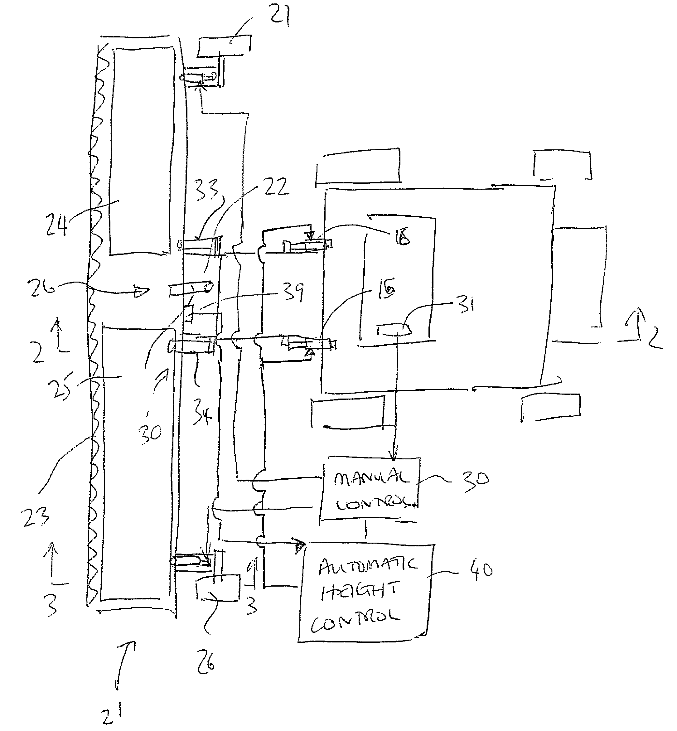
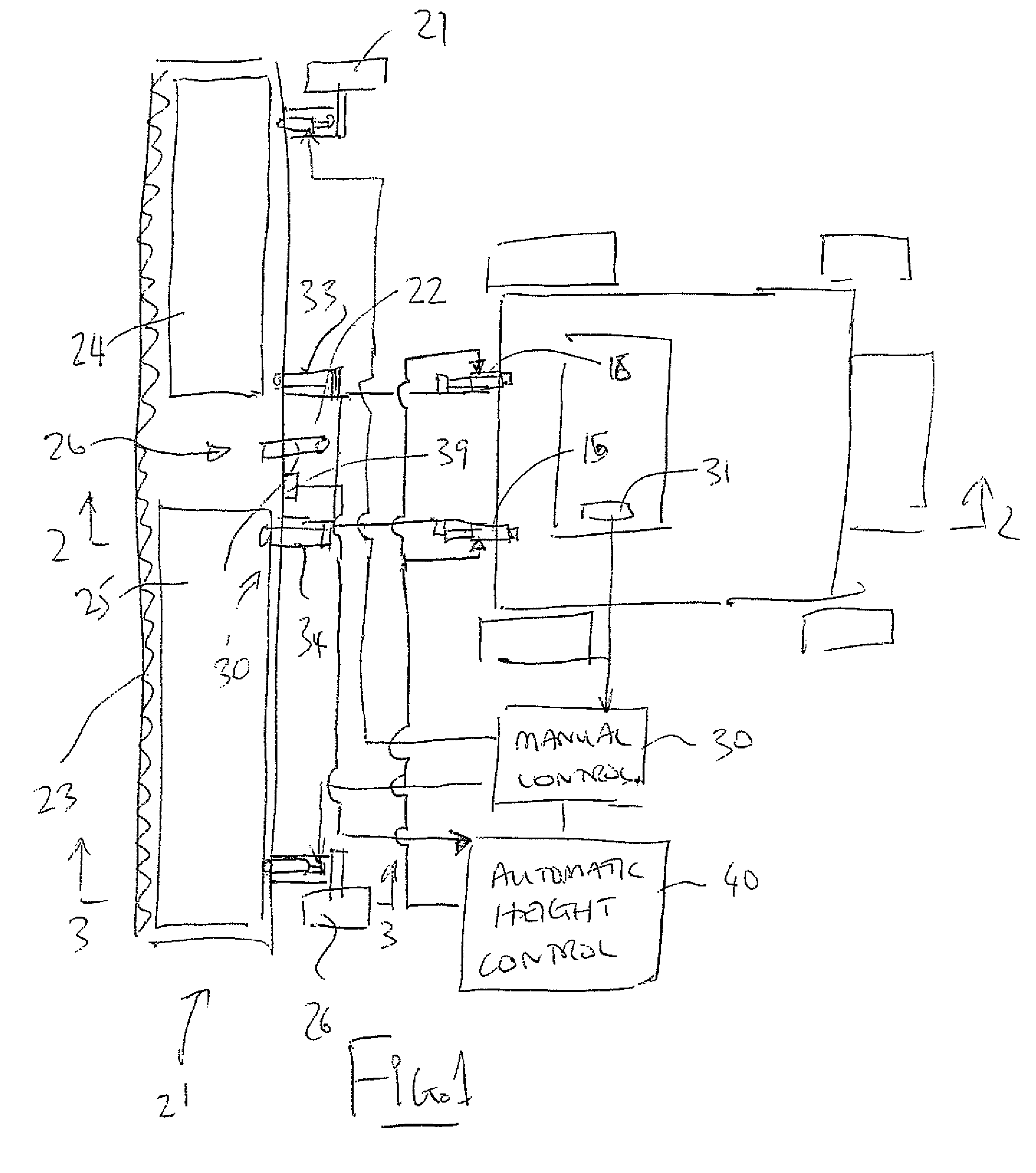
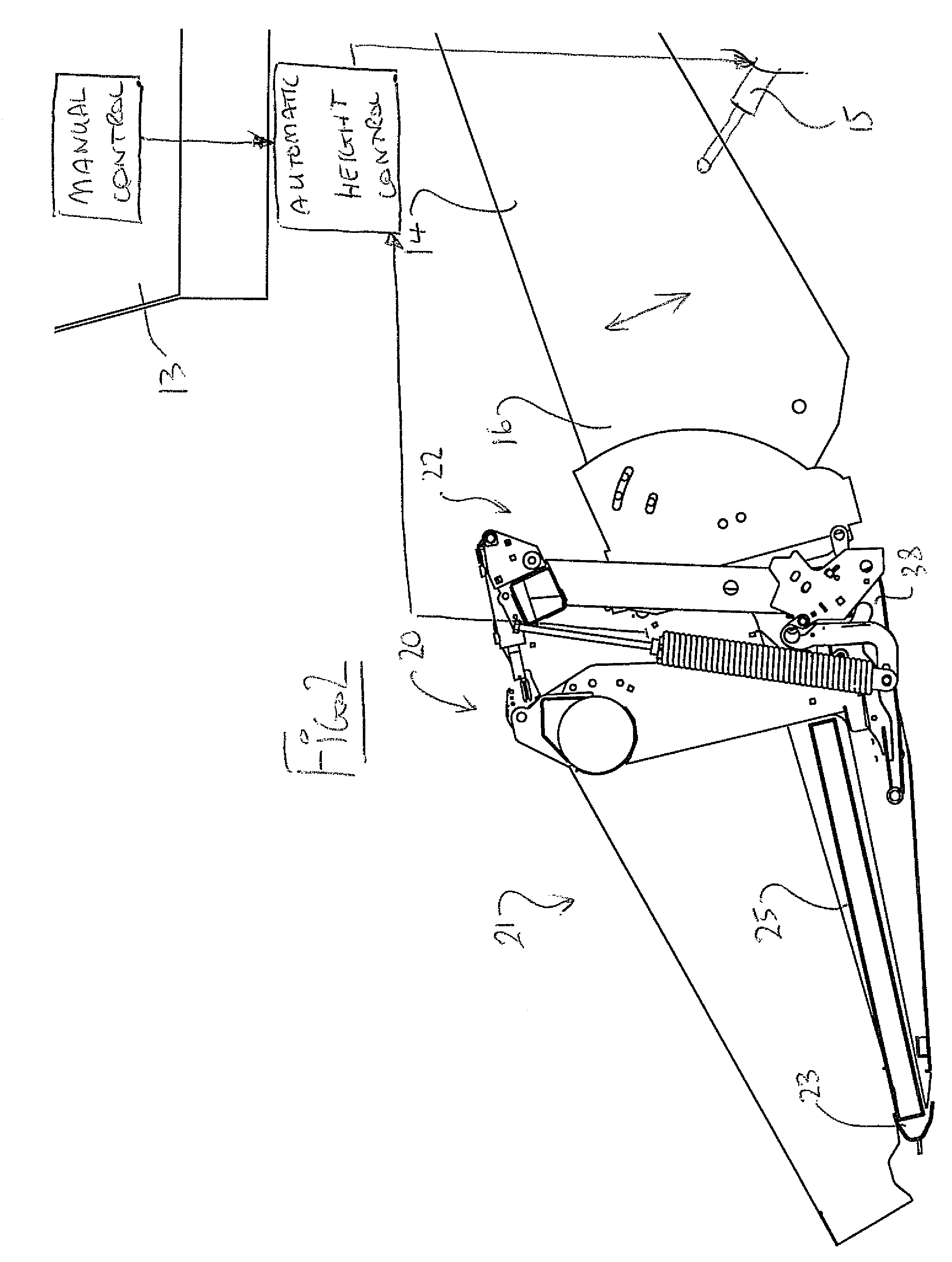
[0049]A combine harvester is shown schematically at 10 and includes ground wheels 11, a main housing 12 containing the crop processing devices, a cab 13 for the operator and a feeder house 14 for receiving the crop material and feeding it into the housing for processing. The details of combine harvesters are well known to a person skilled in this art so that no detail is necessary for an understanding of this invention.

[0050]The feeder house is mounted on the housing in a manner which allows it to be raised and lowered to lift the header carried on the front of the combine. For example the feeder house includes cylinders 15 which raise and lower the front end 16 of the feeder house.

[0051]The present invention is particularly directed to the construction of the header assembly 20 for attachment to the feeder house of the combine harvester.

[0052]The whole header assembly 20 includes a header 21 and an adapter or connector 22 which connects the header to the feeder house so that the fe...


PUM


Abstract

A header assembly for a combine harvester includes a header carried by an adapter on the feeder house of the combine and on a pair of gauge wheels which can be adjusted from inside the cab to change a height of the cutter bar from the ground. This is used in combination with an Automatic Header Height Control so that the main suspension is adjusted to carry approximately 90% of the header weight, the header is dropped on the ground until the gauge wheels contact the ground, and causes the header to “float” with respect to the main carrier frame and the AHHC is set so that the combine feeder house stops lowering when a pre-set amount of header to adapter separation (float) is achieved with the AHHC operating to maintain this set amount by controlling the height of the feeder house.

Description

[0001]This invention relates to a header for a combine harvester where the header includes ground engaging gauge wheels to provide stability to the header when cutting off the ground.BACKGROUND OF THE INVENTION[0002]Typically headers for combine harvesters are mounted on the feeder house of the combine with the mounting arrangement providing a floating action of the header relative to the feeder house so that the cutter bar can rest on the ground and float over the ground in a cutting action.[0003]In some cases an automatic header height control system is provided with header to feeder house position indicators which allow the header to automatically adjust flotation to ground conditions, eliminating the need for the operator to make constant adjustments.[0004]In some cases however it is desirable to provide a cutting action at a position where the cutter bar is at a raised height so that no stability is provided by engagement with the ground. In this arrangement, the header is typi...

Claims


Application Information

Patent Timeline
Patent Type & Authority Patents(United States)
IPC IPC(8): A01D41/14
CPCA01D41/141
Inventor TALBOT, FRANCOIS R.
Owner MACDON INDS
Learn More