
Method for controlling a creeping process and drive train configured for such method

a technology of creeping process and drive train, which is applied in the direction of gearing elements, clutches, gearing, etc., can solve the problem of physical inability to adjust the speed at all, and achieve the effects of reducing fuel burn and operation, surprisingly robust control, and saving energy

Active Publication Date: 2012-08-14
SCHAEFFLER TECH AG & CO KG
View PDF2 Cites 1 Cited by
  • Summary
  • Abstract
  • Description
  • Claims
  • Application Information

AI Technical Summary

Benefits of technology

[0007]Thus, it is an object of the invention to propose a drive train and a method for controlling a creeping process through the drive train, which provide reduced fuel burn and operation with an acceptable pre-determinable creeping velocity. Herein, in particular, energy savings through using a long start-up gear with a hard torque converter shall be implemented.
[0008]The object is accomplished through a method for controlling a creeping process in a drive train, comprising an internal combustion engine, a torque converter and an automated transmission, wherein the internal combustion engine and the torque converter can be decoupled from one another through a separation clutch, and the separation clutch is operated at least partially slipping during the creeping process. Through the method, the speed of the pump shell and thus of the turbine shell is decoupled from the combustion engine, so that a creeping velocity caused by a respective long gearing of the startup gear in combination with a hard torque converter can be converted to a lower pump shell speed to be transmitted to the pump shell through the slippage generated by means of the separation clutch between the crankshaft of the internal combustion engine and the pump shell of the torque converter. Thus, a speed of the combustion engine is simulated at the pump shell or generated, which speed is physically not adjustable at all at the combustion engine. This way, the torque converter can be configured hard in spite of a long gearing of the startup gear, without exceeding a desired creeping velocity of, e.g., 5 to 10 km per hour, which corresponds to a speed transmitted to a drive wheel through the transmission.
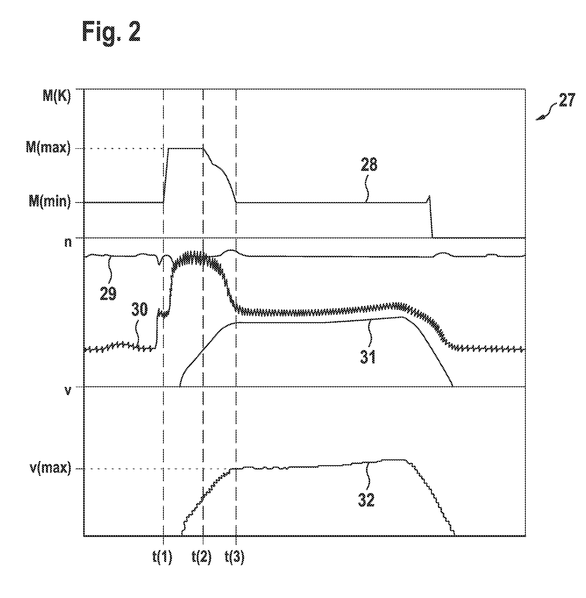
[0009]In particular, in combination with the properties of a torque augmentation of the torque converter when using a stator shell, a slip rate between the combustion engine and the torque converter can be configured at least in two stages. This means, that in order to start the creeping process, the separation clutch can be controlled to a maximum predetermined creeping torque, and the creeping torque can be controlled downward when a maximum creeping velocity is reached, while maintaining the creeping velocity. The control is surprisingly robust, since the load generated by the torque converter is also reduced as a function of speed. The creeping torque which is regulated downward still suffices to maintain the creeping velocity due to the torque augmentation of the torque converter.
[0010]Through the slippage rate of the separation clutch, which is adjustable over a wide range, the creeping velocity can be freely adjusted or preselected over a wide velocity range. The creeping velocity can, e.g., be adjusted as a function of a predetermined driving program, wherein respective driving programs can, e.g., be a sport, comfort, winter, or similar program. Alternatively or additionally, the creeping velocity can be individually adjustable by a driver, e.g., by means of a switch, slide controller or by a selection menu of a vehicle control. It is also advantageous that protective functions influence the creeping velocity, e.g., in order to keep the thermal loading of the separation clutch within limits.
[0011]Furthermore, the object is achieved by a drive train for a motor vehicle, comprising a combustion engine, a torque converter and an automated transmission with plural gears, and a separation clutch coupling a combustion engine and a torque converter, wherein with a separation clutch, which is completely closed during a startup process, with short gearing, this means, low gearing, and with a combustion engine operated at idle, a larger velocity is achieved than a maximum creeping velocity. By using a hard converter and / or a long gearing for the startup process, velocities can be achieved, which can only be controlled through the slippage of the separation clutch to an acceptable creeping velocity during idle of the internal combustion engine. Accordingly, the separation clutch is operated with slippage, in order to adjust the creeping velocity.
[0012]Thus, the creeping velocity can be set in a manner depending on the properties of the torque converter, so that the slippage of the separation clutch is adjusted through the torque converter as a function of the augmentation of the transferable torque. Thus, e.g., while maintaining a predetermined creeping velocity, the slippage of the separation clutch can be adjusted as a function of a characteristic of the torque transferable through the torque converter as a function of the speed of the pump shell, as a function of the speed of the turbine shell or as a function of the slippage between the two of them. Since the torque transferable through the torque converter increases with speed, the slippage of the separation clutch can, e.g., be increased through the torque converter with increasing transferable torque at constant creeping velocity. Thus, the speed of the combustion engine can be kept substantially constant during the creeping process, e.g., at idle speed.

Problems solved by technology

Thus, a speed of the combustion engine is simulated at the pump shell or generated, which speed is physically not adjustable at all at the combustion engine.

Method used


Image

  • Method for controlling a creeping process and drive train configured for such method
  • Method for controlling a creeping process and drive train configured for such method
  • Method for controlling a creeping process and drive train configured for such method

Examples


Embodiment Construction

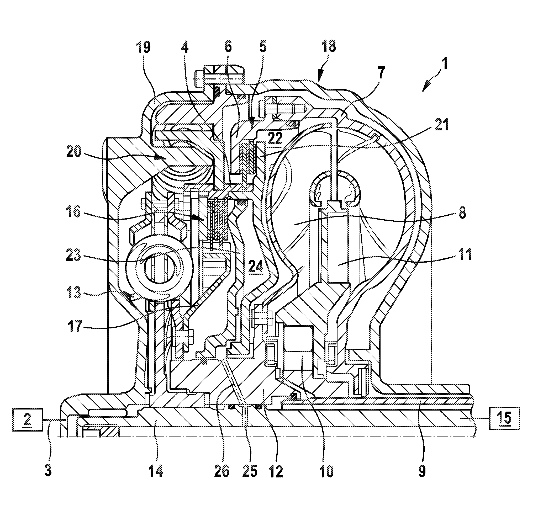
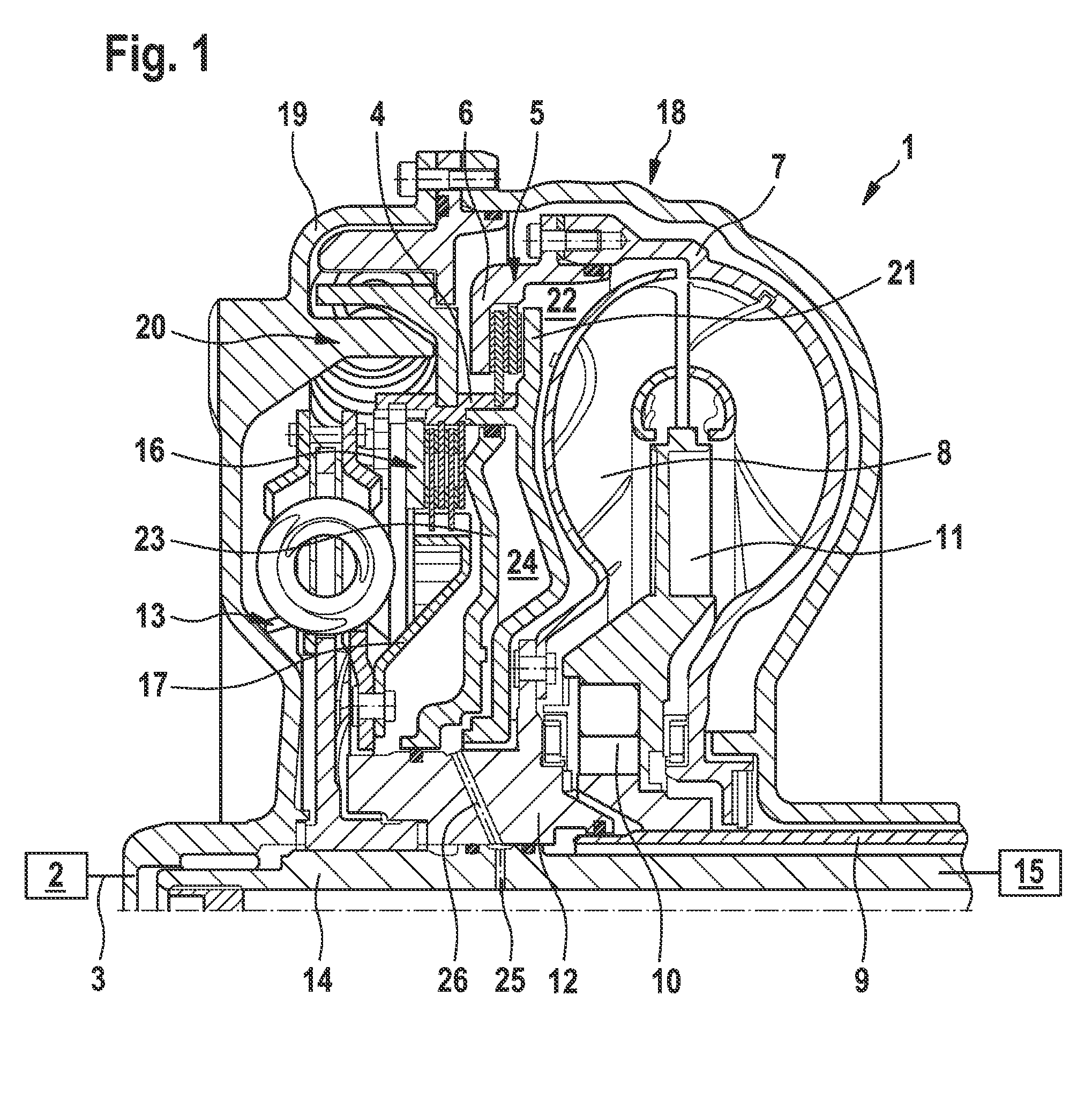
[0016]FIG. 1 shows a partially schematically illustrated drive train 1 with an internal combustion engine 2 with a crankshaft 3, which is connected to the input component 4 of a separation clutch 5. The output component 6 of the separation clutch 5 can be connected to the pump shell 7. The pump shell 7 drives a turbine shell 8 and a stator shell 11, disposed at the converter neck 9 and fixed to the housing by means of a freewheeling clutch 10. The turbine shell 8 is connected non-rotatably to the transmission input shaft 14 of the automated transmission 15 by means of the turbine hub 12, which simultaneously forms the input component 17 of the turbine damper 13. When the separation clutch 5 is closed, the converter lockup clutch 16 connects the pump shell 7 with the input component 17 of the turbine damper 13, so that a high slippage between the pump shell 7 and the turbine shell 8 is preferably avoided at higher speeds of the pump shell 7, and so that the torque transmitted from th...


PUM


Abstract

A drive train of a motor vehicle with an internal combustion engine, a torque converter and a transmission, wherein a separation clutch is provided between the internal combustion engine and the torque converter. In order to be able to perform a creeping process at a certain creeping velocity, the separation clutch is operated slipping. This way, the gearing of the startup process can be configured long, even when using a so-called hard torque converter, without having to tolerate a creeping velocity, which is too high.

Description

CROSS-REFERENCE TO RELATED APPLICATIONS[0001]This patent claims priority of German Patent Application No. 10 2008 027 072.5, filed on Jun. 5, 2008, which application is incorporated herein by reference.FIELD OF THE INVENTION[0002]The invention relates to a drive train with an internal combustion engine, a torque converter and an automated transmission, and it relates to a separation clutch, disposed between the internal combustion engine and torque converter, and it relates to a method for controlling a creeping process for such drive trains.BACKGROUND OF THE INVENTION[0003]Automated transmissions are known, in which an internal combustion engine directly drives a torque converter as a start up element, which converts the input torque and transfers it to the automated transmission. Torque converters are thus configured in hydrodynamic construction with a pump shell directly driven by the internal combustion engine and with a turbine shell driven by the pump shell through an operatin...

Claims


Application Information

Patent Timeline
Patent Type & Authority Patents(United States)
IPC IPC(8): B60W10/02
CPCF16D48/06F16H61/143F16H61/20F16D2500/50206F16D2500/70426Y10T477/78F16H2061/145F16H2061/202F16H2045/002Y10T477/755Y10T477/6425F16H2312/06
Inventor KLUMP, MARKUSVORNEHM, MARTINLANG, DIETMAR
Owner SCHAEFFLER TECH AG & CO KG
Learn More