
Visual interface for automated software testing

a software testing and visual interface technology, applied in the direction of instrumentation, program control, electric digital data processing, etc., can solve the problems of software testing being seen as an obstacle to production, software developers often spend a great deal of time and money testing, and the cost of not testing is increased, so as to increase the usability of the action window

Active Publication Date: 2012-08-07
MICRO FOCUS IP
View PDF13 Cites 37 Cited by
  • Summary
  • Abstract
  • Description
  • Claims
  • Application Information

AI Technical Summary

Benefits of technology

The system enables novice users to perform automated software testing efficiently by providing a visual interface for creating and editing tests, reducing the need for technical expertise and allowing offline editing, with clear results and collaboration features.

Problems solved by technology

Software developers commonly spend a great deal of time and money testing the computer programs they develop.
Software testing is viewed as an obstacle to production because it is time consuming and the costs of not testing are theoretical and uncertain.
Consequently, software testing is often neglected.
As software becomes increasingly more complex, testing the software also becomes more complex as a large number of unique combinations of paths and modules may be tested for each program.
Maintaining test scripts and interpreting test results can be inefficient because of the abstraction inherent in scripting.
Users cannot “see” what they are trying to do with the application being tested, and as a result they sometimes spend significant amounts of time identifying required changes and verifying that changes function as expected.
However, the user is not provided with a visual interface for understanding the relationship of each action and each window to the overall scope of the script.
Further, technical language is still used in much of the text presented to the user, making it difficult for non-technical personnel to make use of such tool.
Notwithstanding existing approaches to making application testing easier for non-technical users, challenges have remained.
This is an important need because it is often Subject Matter Experts (SMEs) for a particular application that could best serve as testers for such application, yet such SMEs are rarely qualified to serve as software quality assurance testers using existing test products.

Method used


Image

  • Visual interface for automated software testing
  • Visual interface for automated software testing
  • Visual interface for automated software testing

Examples


Embodiment Construction

[0041]The Figures (“FIG.”) and the following description relate to preferred embodiments of the present invention by way of illustration only. It should be noted that from the following discussion, alternative embodiments of the structures and methods disclosed herein will be readily recognized as viable alternatives that may be employed without departing from the principles of the claimed invention.

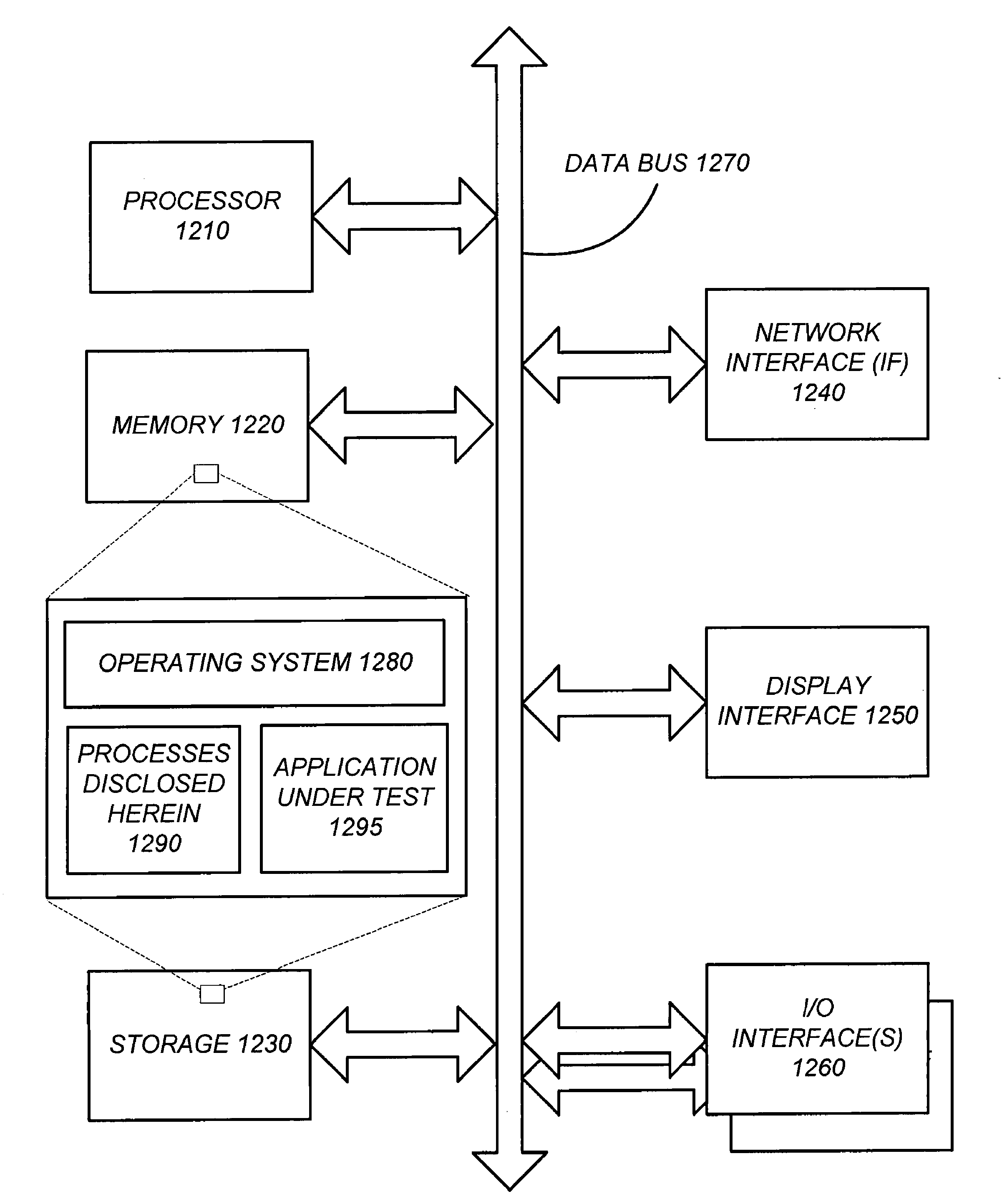
[0042]The present invention includes a system and a method for providing a visual interface for creating, maintaining, and, reviewing the results of, automated functional tests of software applications. The system includes actual screen views for each window that is automated within the application under test. FIG. 12 illustrates an overall flow diagram of one embodiment of this invention with the processes disclosed herein 1290 in one embodiment stored in the storage medium 1230 of a computer, and then copied to memory 1220 during execution.

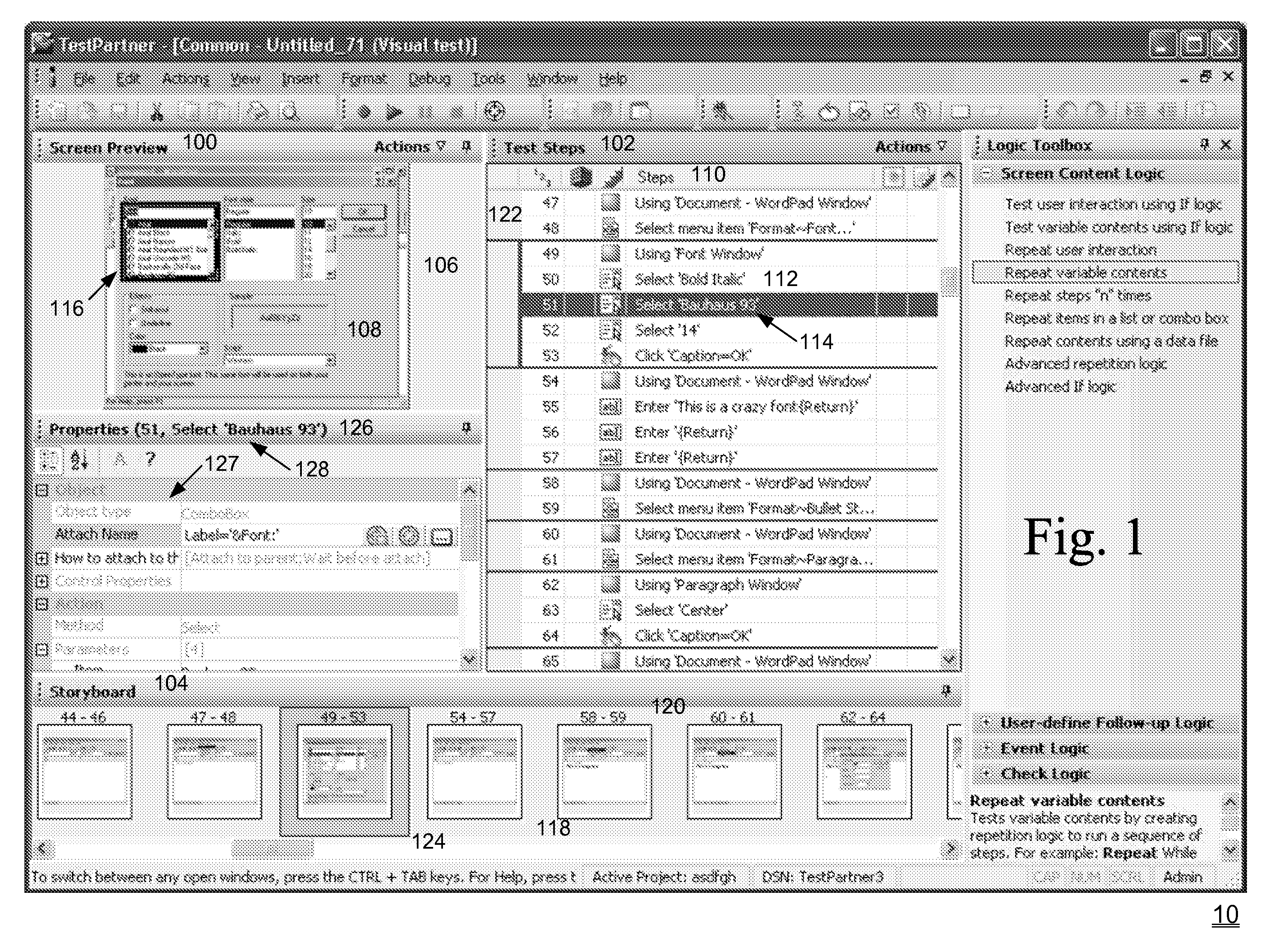
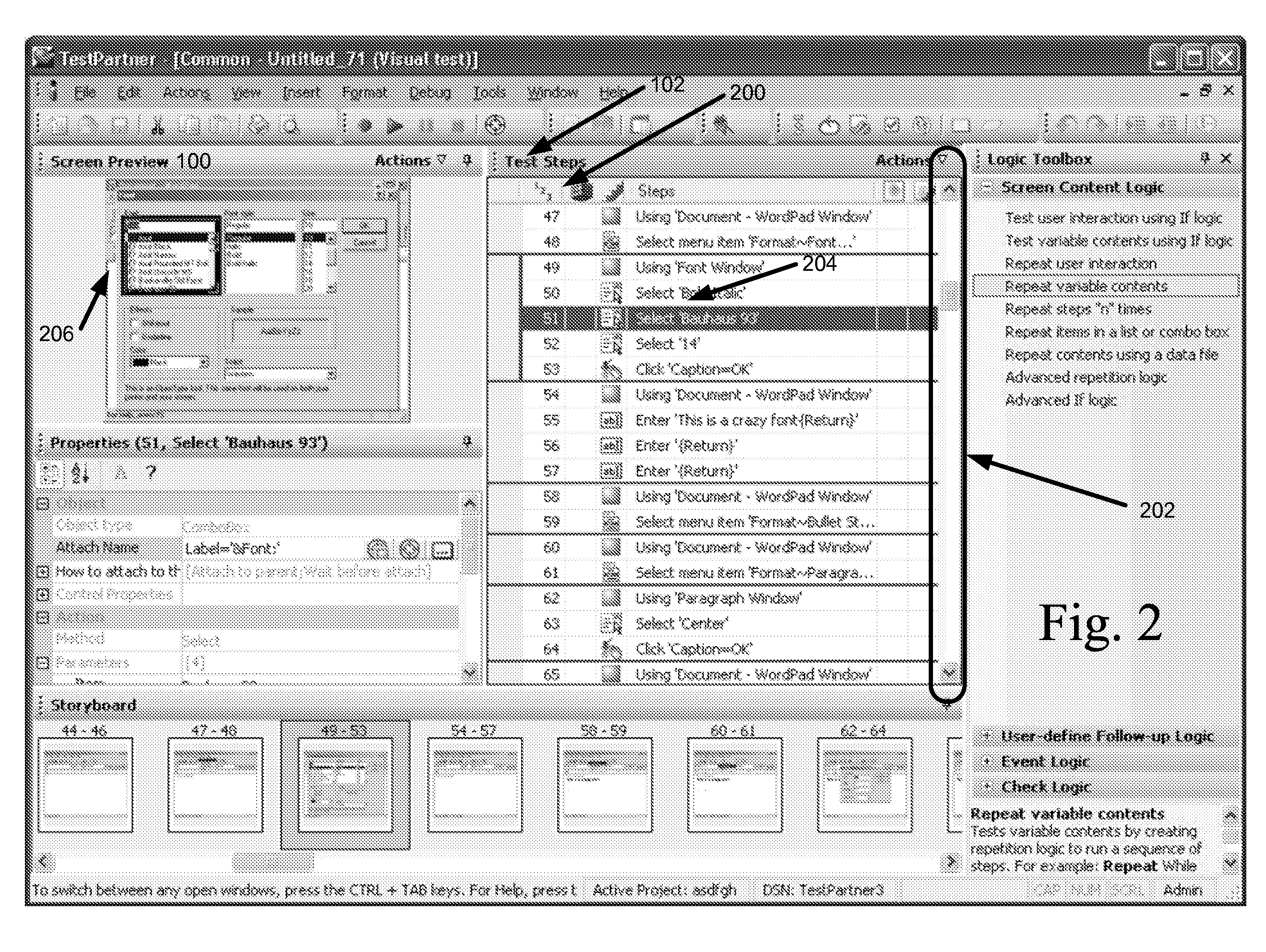
[0043]FIG. (“FIG.”) 1 illustrates an embodimen...


PUM


Abstract

A system and a method of providing a visual interface for creating, maintaining, and reviewing the results of, automated functional tests of software applications that includes screen views for each window automated within the application under test. The system and method provide a visual interface for creating and modifying functional tests of software applications geared for novice users. The visual interface includes a screen preview, test steps, properties and a storyboard. A test logic builder interface enables novice users to add logic, including verification and synchronization, to their visual test transactions without having to understand programming concepts.

Description

BACKGROUND OF THE INVENTION[0001]1. Field of the Invention[0002]This invention relates generally to automated testing of computer software programs and more particularly to automated software quality through automated functional testing using graphical user interfaces.[0003]2. Description of the Related Arts[0004]Software developers commonly spend a great deal of time and money testing the computer programs they develop. This is especially true for development of so-called “mission critical” programs, such as those used in business accounting, payroll and billing systems.[0005]Software testing is viewed as an obstacle to production because it is time consuming and the costs of not testing are theoretical and uncertain. Consequently, software testing is often neglected. One way to balance deployment time with higher software quality resulting from thorough testing is to make testing and development as efficient as possible.[0006]As software becomes increasingly more complex, testing ...

Claims


Application Information

Patent Timeline
Patent Type & Authority Patents(United States)
IPC IPC(8): G06F9/45
CPCG06F11/3664
Inventor BRENNAN, JAMES M.SALIH, ERGIN A.HARFOUCH, KHALIL N.FAUBERT, RUSS D.
Owner MICRO FOCUS IP
Learn More