
Fitting and verification procedure for direct bone conduction hearing devices

a technology of hearing aids and fittings, applied in the field of fitting and verification procedures of direct bone conduction hearing devices, can solve the problems of not being able to provide valid and reliable verification procedures for direct bone conduction hearing aids, not being able to inform clinicians about speech aided audibility,

Inactive Publication Date: 2012-07-17
OSSEOFON
View PDF7 Cites 1 Cited by
  • Summary
  • Abstract
  • Description
  • Claims
  • Application Information

AI Technical Summary

Benefits of technology

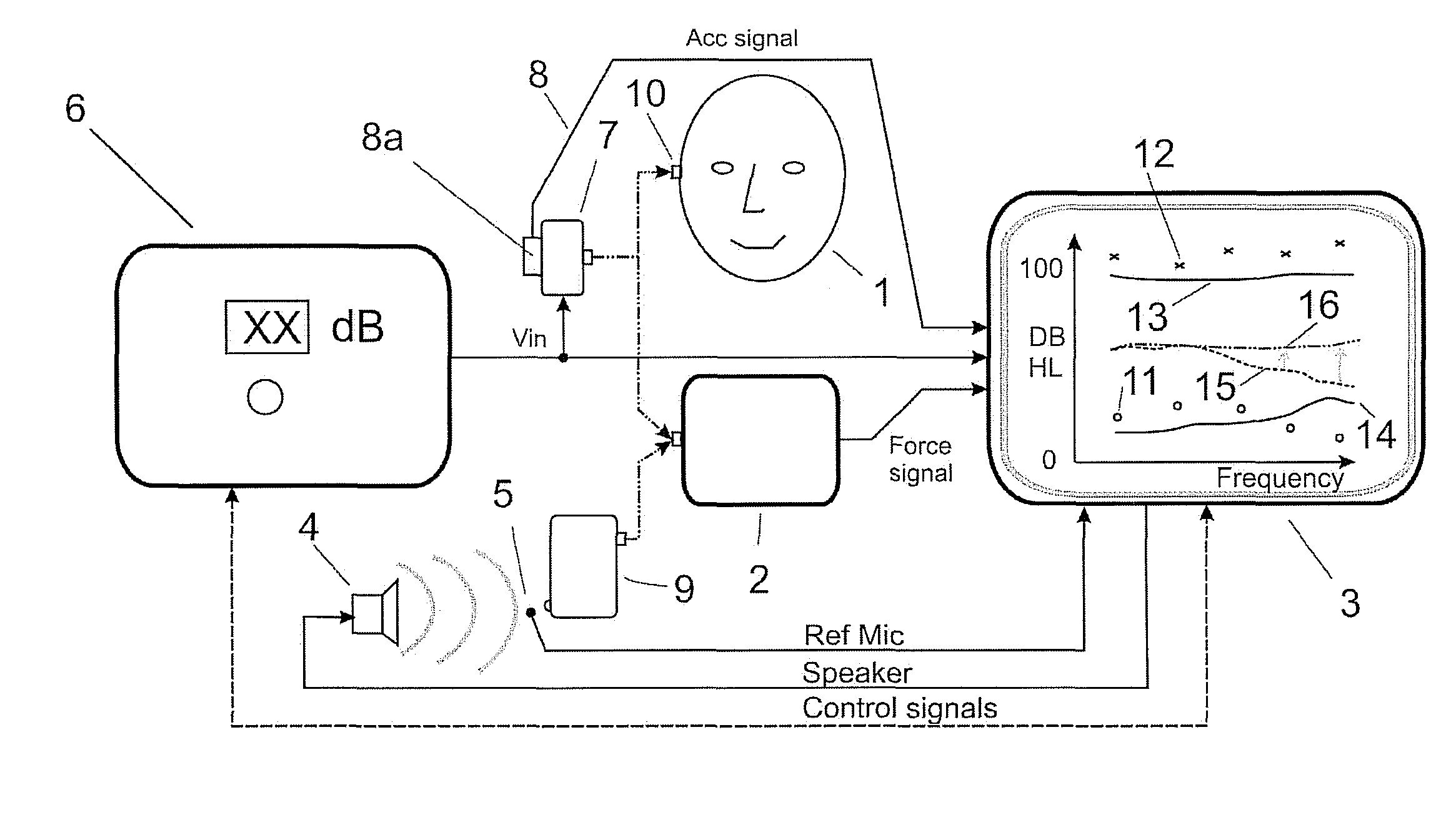
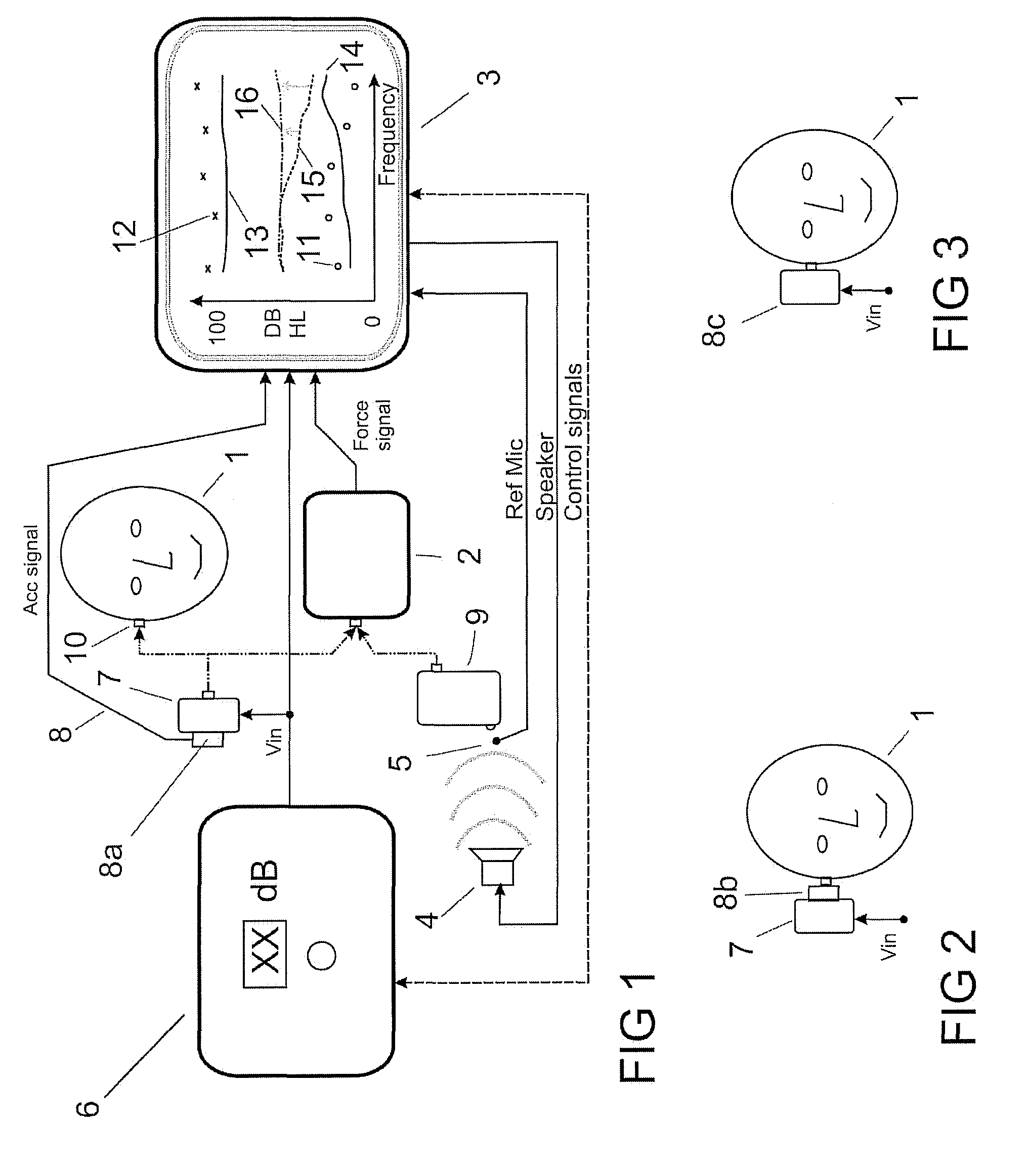
[0046]In addition, the hearing threshold 11 and LDL 12 are displayed in the audio test station 3 also some hearing device characteristics are measured and displayed like maximum power output (MPO) 13 and noise floor 14. Also the hearing device output 15 at a certain acoustical input can be measured and displayed. By comparing these data a trained audiologist can adjust the device characteristics to improve the hearing rehabilitation in that particular patient.

Problems solved by technology

Not all individuals can wear air conduction hearing aids.
Despite being clinically available for many years, valid and reliable verification procedures for direct bone conduction hearing aids have not emerged.
While aided soundfield thresholds do offer the clinician insight into the softest tones a person can hear in the aided condition, they do little to inform the clinicians about the aided audibility of speech.
Moreover, aided soundfield thresholds tell you nothing about the output limits of the device and are known to be unreliable (see Hawkins, 2004; Seewald et al., 1996).

Method used


Image

  • Fitting and verification procedure for direct bone conduction hearing devices
  • Fitting and verification procedure for direct bone conduction hearing devices

Examples


Embodiment Construction

Definitions

Direct Bone Conduction Hearing Device:

[0013]Direct bone conduction hearing devices are defined as devices where the vibration transducer is rigidly attached to the skull bone without intervening soft tissues. These devices can be either percutaneous (i.e. using a skin penetrating abutment attached to a fixture integrated to the skull bone) or transcutaneous (where at least the driving side of the transducer is attached subcutaneously to the skull bone). Such subcutaneously placed transducers has an outer housing made of titanium.

Sound Pressure Levels (SPL):

[0014]When possible the Sound Pressure Level (SPL) is used as the objective measure where the SPL dB is referred to 20μ Pascal.

Acceleration Levels (A):

[0015]For bone conduction applications (hearing via the skull bone) Acceleration can be used as the objective measure where the A dB is referred to 1 m / s2.

Force Levels (F):

[0016]Sometimes the Force is used instead of Acceleration and the F dB is then referred to 1μ Newton...


PUM


Abstract

The present invention relates to a method for fitting and verification of direct bone conduction hearing devices to a patient, whereina. in a first step the hearing threshold and loudness discomfort levels are measured directly on a titanium implant of a patient,b. in a second step these hearing threshold and loudness discomfort levels are converted to equivalent force thresholds (FHT) and loudness discomfort levels (FLDL) on an artificial skull force measuring device,c. in a final step the output force levels of the direct bone conduction hearing device is measured in a free sound field with the device attached to the said artificial skull force measuring device and compared to the FHT and the FLDL as the base for final adjustments of the device.

Description

PRIORITY INFORMATION[0001]This application claims priority to Swedish Application No. 070629-7, filed on Nov. 28, 2007 and Swedish Application No. 0702894-7, filed on Dec. 21, 2007, both applications are incorporated herein by reference in their entireties.DESCRIPTION[0002]1. Technical Field[0003]The present innovation is intended as a method to improve the fitting procedure in direct bone conduction hearing devices. Direct bone conduction devices are used most frequently in patients who cannot use conventional air conduction devices because of chronic external ear or middle ear infections or in patients with malformations.[0004]2. Background to the Invention[0005]A main goal for verifying the appropriateness of any hearing aid fitting should be to match, as closely as possible, the amplification characteristics of the hearing aid to the unique auditory characteristics of the hearing impaired listener. Each hearing impaired listener will have a unique dynamic range of hearing. The d...

Claims


Application Information

Patent Timeline
Patent Type & Authority Patents(United States)
IPC IPC(8): H04R29/00
CPCA61B5/1101A61B5/121H04R25/70A61B2562/0219H04R2460/13
Inventor HAKANSSON, BOHODGETTS, WILLIAM
Owner OSSEOFON
Learn More