
Break-away adapter

a technology of adapters and break-away cables, which is applied in the direction of one-pole connections, coupling device connections, coupling parts engagement/disengagement, etc., can solve the problems of time-consuming installation, affecting electrical and mechanical performance, and affecting the electrical and mechanical performance of the system, so as to achieve easy disengagement, and easy disengagement and disengagement

Inactive Publication Date: 2012-07-17
SOURIAU USA
View PDF20 Cites 29 Cited by
  • Summary
  • Abstract
  • Description
  • Claims
  • Application Information

AI Technical Summary

Benefits of technology

"The invention is about an adapter that can be used with a threaded connector assembly. The adapter has a receptacle body and a locking sleeve that can be easily engaged or disengaged from the connector assembly. This allows for easy removal of the connector assembly from the adapter without damaging it. The locking sleeve has mounting projections that exert sufficient force on the connector assembly to provide a secure physical and electrical connection. The adapter can be easily engaged and disengaged from the connector assembly, allowing for a break-away style connection. The invention also includes a contact assembly that provides an electrical connection between the male and female contacts of the connector assembly. The locking sleeve of the adapter can be easily engaged and disengaged from the connector assembly, allowing for a force applied to the first or second portion of the connector assembly to disengage the second portion without damaging it. The invention also includes a coaxial adapter for use with a coaxial connector assembly."

Problems solved by technology

While existing connectors work relatively well, they are time-consuming to install.
In addition, temperature cycling and / or rotational torque applied to the cable assembly can cause the threaded nut to back off, negatively impacting electrical and mechanical performance.
Also, the existing connectors do not allow the male portion to be disengaged or break away from the female connector if a harmful force is applied to either connector, thereby creating the possibility that the connector portions or the system will be damaged if an inappropriate force is applied thereto.

Method used


Image

  • Break-away adapter
  • Break-away adapter
  • Break-away adapter

Examples


Embodiment Construction

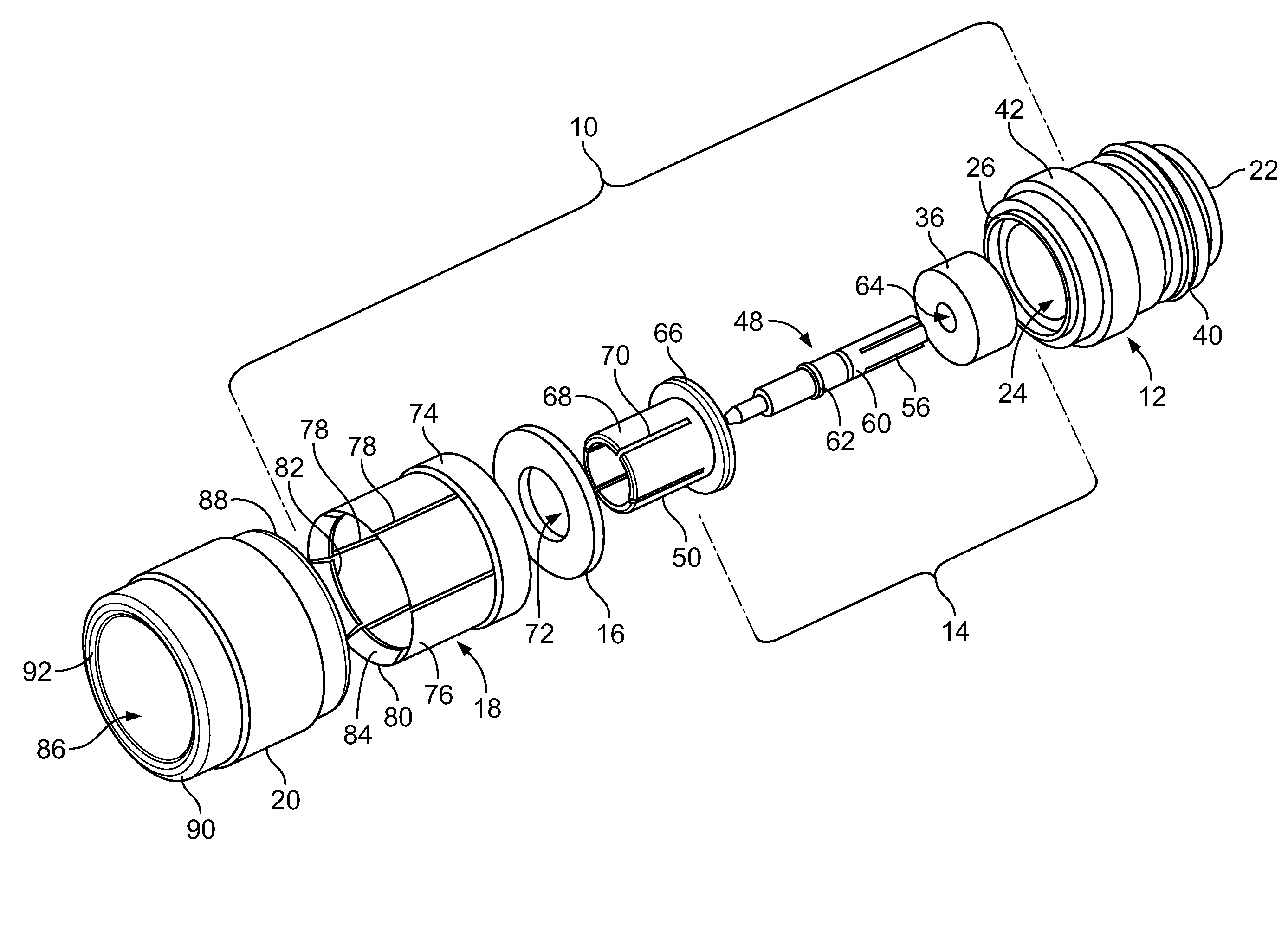
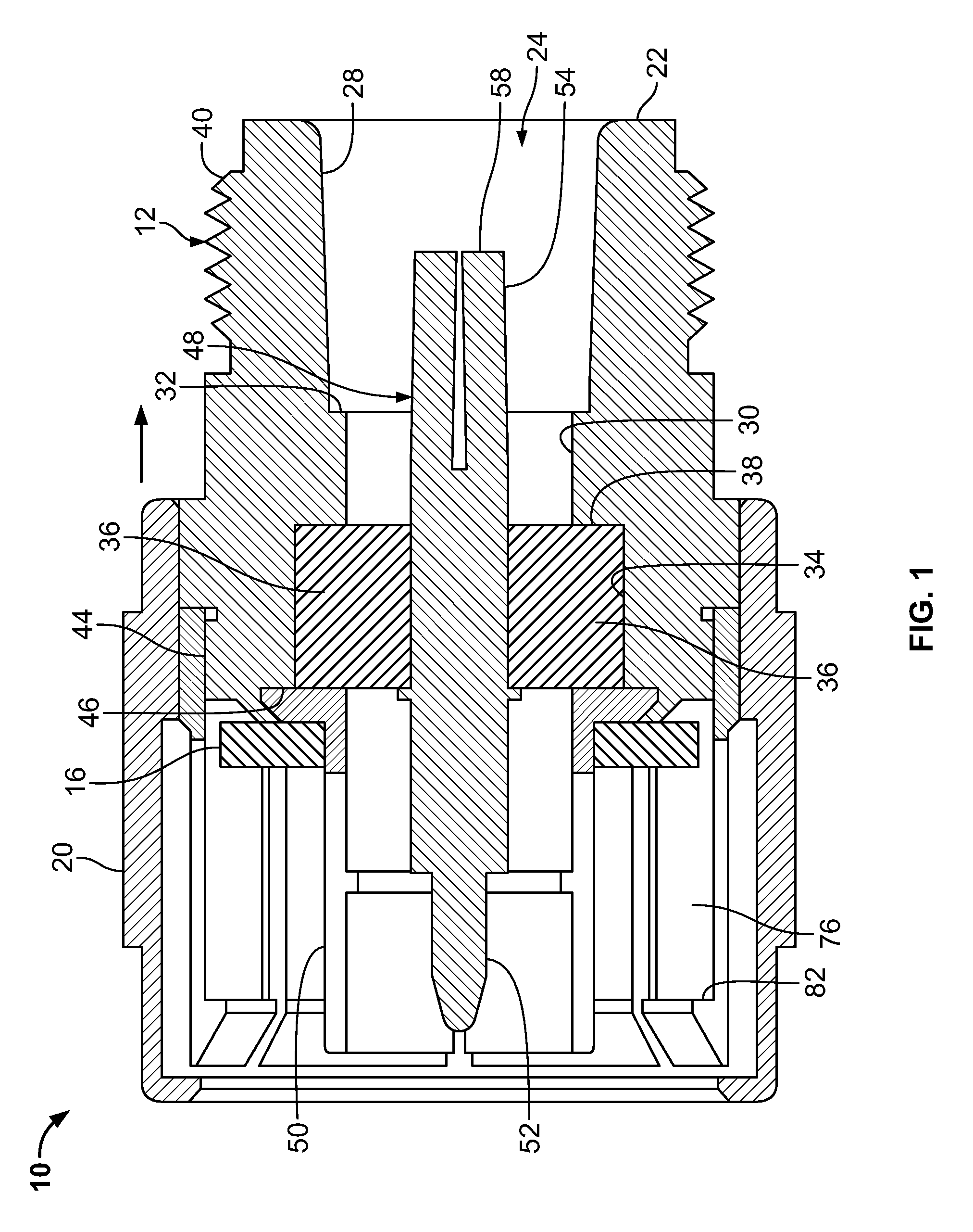
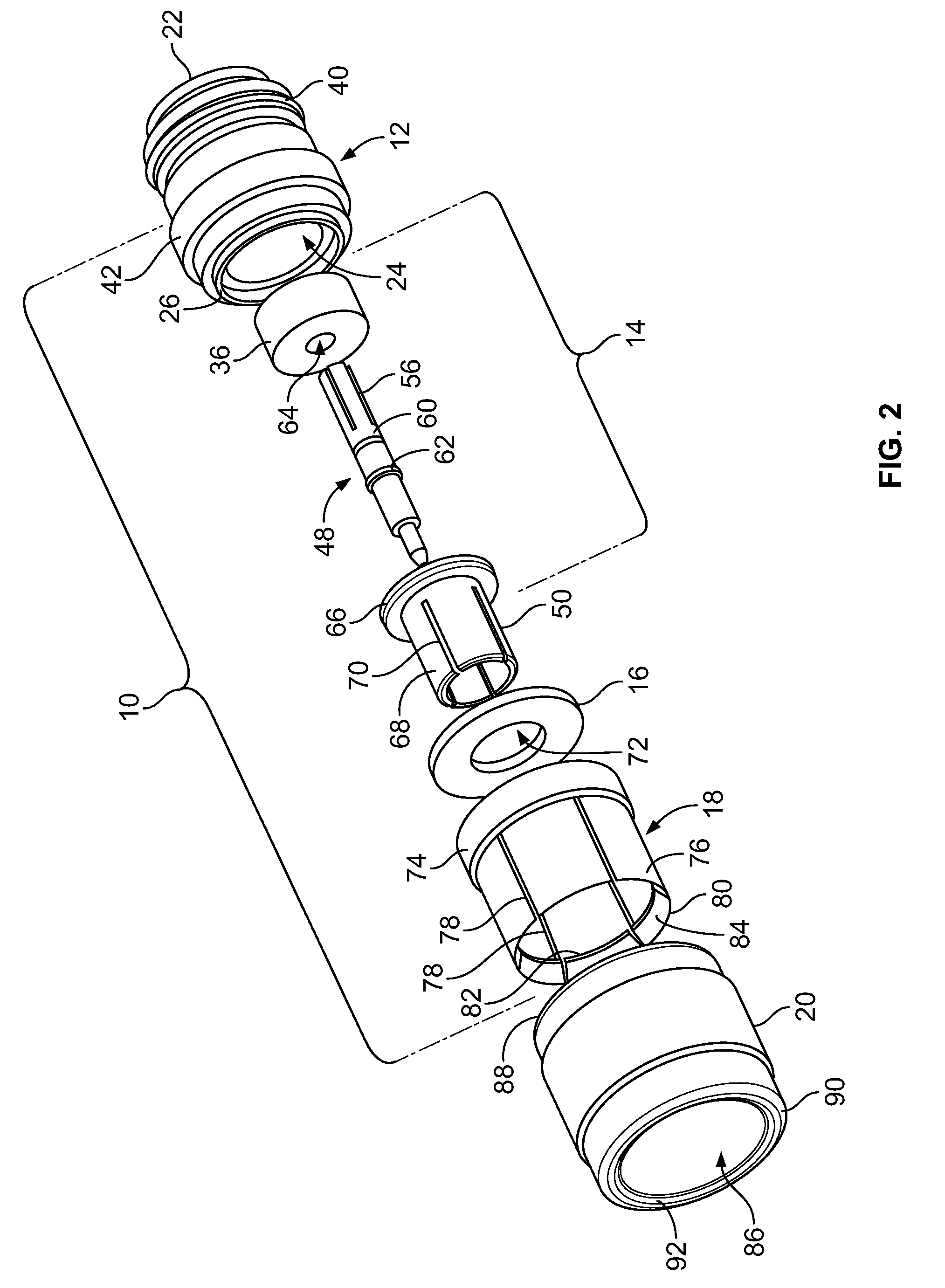
[0017]An adapter 10 for use with an N-series coax connector 100, 200 (FIGS. 5 and 6) is disclosed. As best shown in FIG. 2, the adapter 10 has a receptacle body 12, a coaxial contact assembly 14, a gasket 16, a locking sleeve 18 and a shell 20. In general, the N-series coax connector to which the adapter 10 is mated is an N-series coax connector known in the art with a known male portion 100 and a known female portion 200. When mated together, the male portion 100 is threaded to the female portion 200, thereby securing the male portion to the female portion. As the N-series coax connectors are known connectors, such connectors are incorporated herein by reference and a further description of the N-series coax connectors will not be provided.

[0018]The receptacle body 12 of the adapter 10 is made from metal or other electrically conductive material which has the strength characteristics required. The receptacle body 12 has a generally cylindrical configuration. As best viewed in FIG. ...


PUM


Abstract

The invention is directed to an adapter for use with a connector assembly. The adapter has a receptacle body and a locking sleeve. The receptacle body is applied to a first portion of the connector assembly, and the locking sleeve is applied to a second portion of the connector assembly. The locking sleeve can be easily disengaged from the receptacle body to remove the second portion or the connector assembly from the first portion.

Description

FIELD OF THE INVENTION[0001]The present invention is directed to an adapter for use with a coaxial connector. The adapter allows the male portion of the connector to be disengaged when a pre-determined force is applied thereto. The adapter is used to convert a standard threaded coupled connector into a push-on and break-away connector.BACKGROUND OF THE INVENTION[0002]Coaxial connectors for radio frequency (rf) signals are known. Such connectors are typically used with a coaxial cable containing an external conductor / shield surrounding one or more internal conductors. The coaxial connector functions to align and provide an electrical path to the respective ends of the conductors while providing a continuous shield to minimize rf leakage. These connectors generally include a female portion and a male portion. The male portion contains the conductor interface and a threaded nut used to engage the female portion.[0003]The female portion includes a tubular housing that functions to accep...

Claims


Application Information

Patent Timeline
Patent Type & Authority Patents(United States)
IPC IPC(8): H01R9/05
CPCH01R13/6277H01R24/542H01R2101/00H01R2103/00
Inventor LEIBFRIED, JR., RICHARD GLENN
Owner SOURIAU USA
Learn More