Internal combustion engine piston
a technology of internal combustion engine and piston, which is applied in the direction of pistons, machines/engines, mechanical apparatus, etc., can solve the problems of large frictional force of pistons and uneven rigidity of the entire skirt, and achieve large frictional force, uneven rigidity of the entire skirt, and enhanced rigidity of the lower end portion of the skirt
- Summary
- Abstract
- Description
- Claims
- Application Information
AI Technical Summary
Benefits of technology
Problems solved by technology
Method used
Image
Examples
first embodiment
[0024]As shown in FIG. 7, a piston 1 is provided in a cylindrical bore formed in a cylinder block 2, so that piston 1 is in sliding contact with a cylinder wall 3 of the bore. Piston 1, cylinder wall 3, and cylinder head not shown define a combustion chamber 4. Piston 1 is linked to a crankshaft not shown through a piston pin 5 and a connecting rod 6.
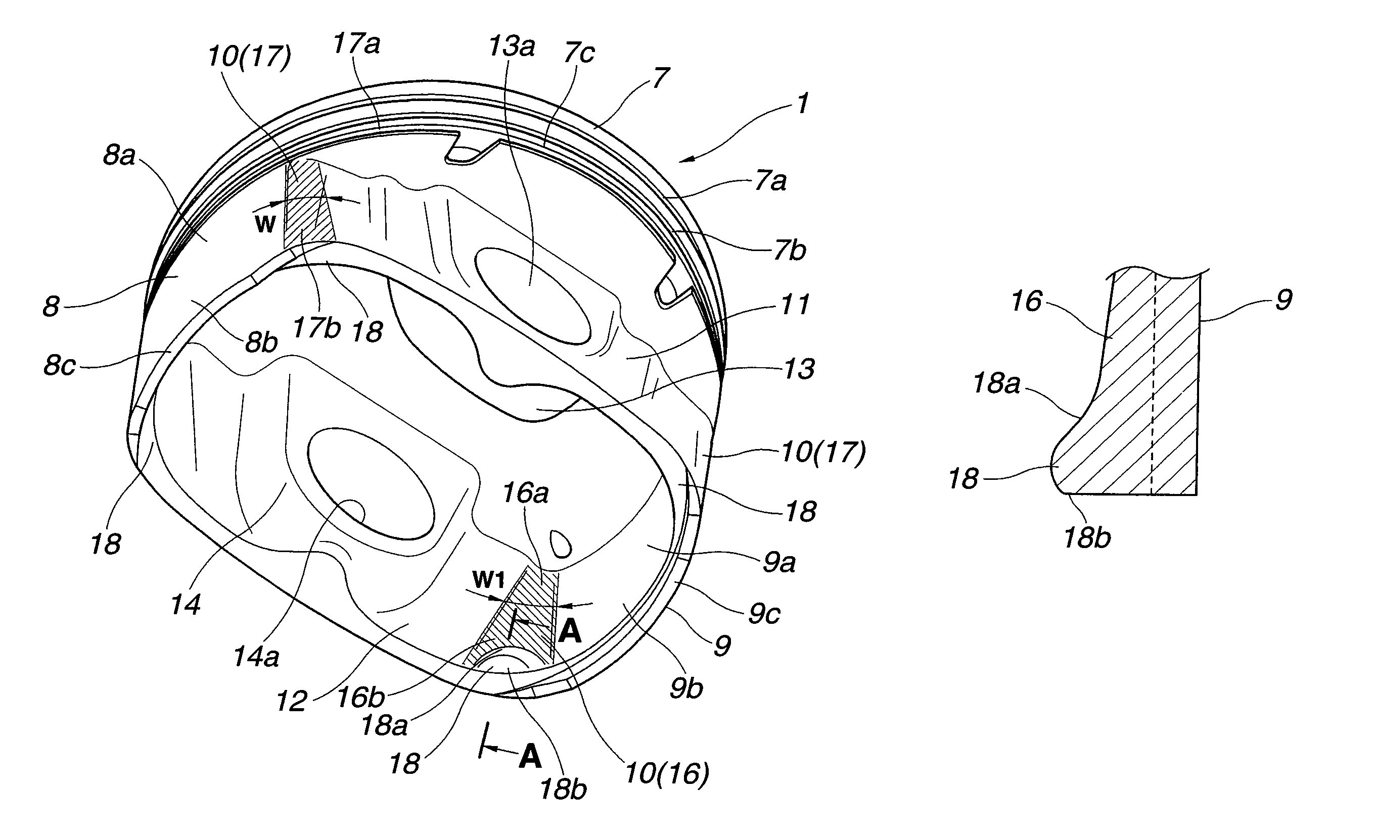
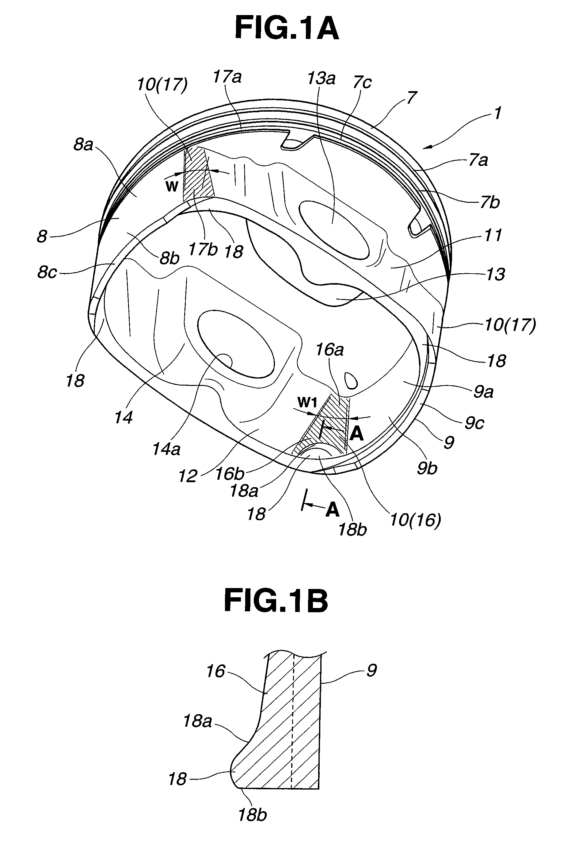
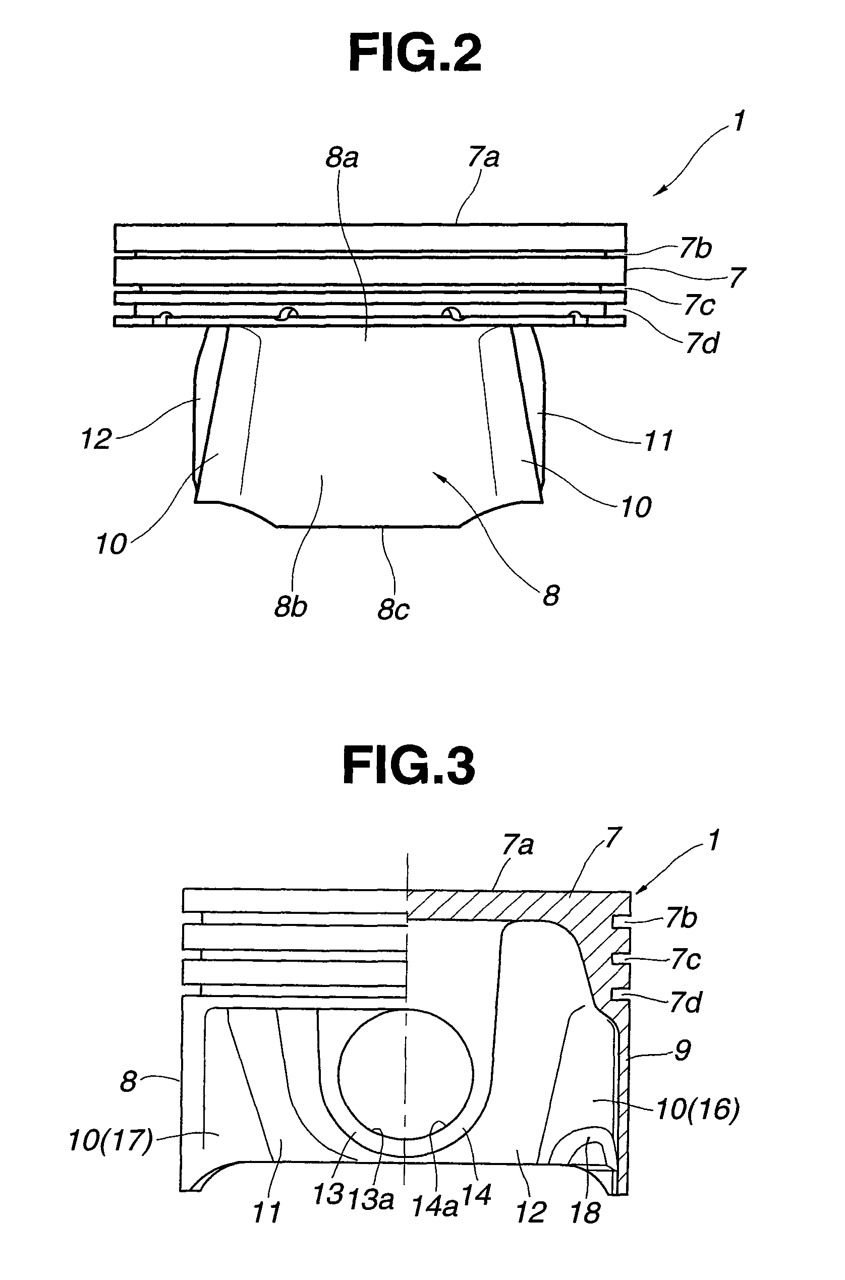
[0025]Piston 1 is formed integrally from an Al—Si aluminum alloy, AC8A, by casting. As shown in FIGS. 1A to 4, piston 1 has a cylindrical shape, which is formed with a piston crown 7 defining the combustion chamber 4 on a crown top 7a; a thrust-side skirt 8 formed integrally with a periphery of a lower end portion of piston crown 7, and adapted to be in sliding contact with cylinder wall 3, wherein thrust-side skirt 8 has an arc-shaped cross-section as viewed in the longitudinal direction of piston 1; an anti-thrust-side skirt 9 formed integrally with the periphery of the lower end portion of piston crown 7, and adapted to be in sliding...
second embodiment
[0040]FIGS. 10 and 11 show a second embodiment in which thrust-side and anti-thrust-side skirts 8 and 9 are formed and arranged asymmetrically with respect to the plane passing through the central longitudinal axis of piston 1. Specifically, the circumferential length X of anti-thrust-side skirt 9 is set shorter than the circumferential length X1 of thrust-side skirt 8. Namely, the contact area of anti-thrust-side skirt 9 with cylinder wall 3 is set smaller than that of thrust-side skirt 8. This is because the pressing force applied to anti-thrust-side skirt 9 is smaller than the pressing force applied to thrust-side skirt 8.
[0041]The radius of curvature of each of two connecting sections 10 closer to thrust-side skirt 8 is set equal to that in the first embodiment. On the other hand, the radius of curvature of each of two connecting sections 10a closer to anti-thrust-side skirt 9 is set smaller than that of connecting sections 10 closer to thrust-side skirt 8.
[0042]Moreover, the th...
third embodiment
[0045]FIGS. 12 to 14 show a third embodiment created based on the first and second embodiments, in which each apron 11 or 12 is curved slightly outwardly as viewed in FIG. 13, extending in parallel to the longitudinal axis of piston 1 with no inclination. Namely, aprons 11 and 12 are arranged in parallel to each other, in contrast to the aprons according to the first embodiment which constitute a truncated cone shape with a trapezoidal side-section.
[0046]The radius of curvature of outside surface 17 of connecting section 10 is substantially constant all over the range from the upper end to the lower end. In contrast, the radius of curvature of inside surface 16 of connecting section 10 is set to increase gradually as followed from upper end portion 16a to lower end portion 16b.
[0047]In this embodiment, the curved shapes of aprons 11 and 12 serve as springs, as in the first embodiment. Moreover, in connecting section 10, the feature that the radius of curvature of outside surface 17...
PUM
 Abstract
Description
Claims
Application Information
 - R&D
- Intellectual Property
- Life Sciences
- Materials
- Tech Scout
- Unparalleled Data Quality
- Higher Quality Content
- 60% Fewer Hallucinations
Browse by: Latest US Patents, China's latest patents, Technical Efficacy Thesaurus, Application Domain, Technology Topic, Popular Technical Reports.
© 2025 PatSnap. All rights reserved.Legal|Privacy policy|Modern Slavery Act Transparency Statement|Sitemap|About US| Contact US: help@patsnap.com


