
Networked control system using logical addresses

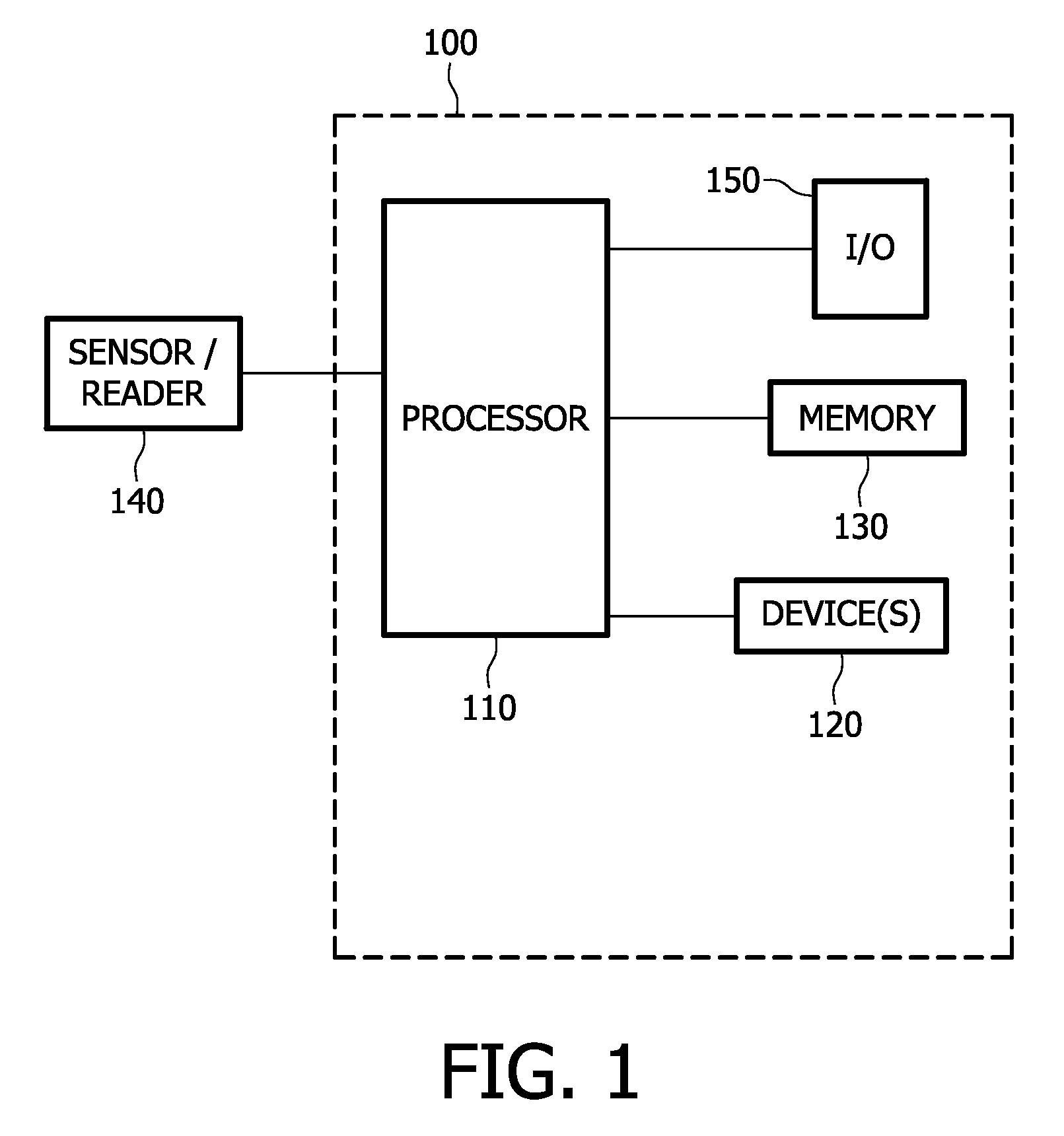
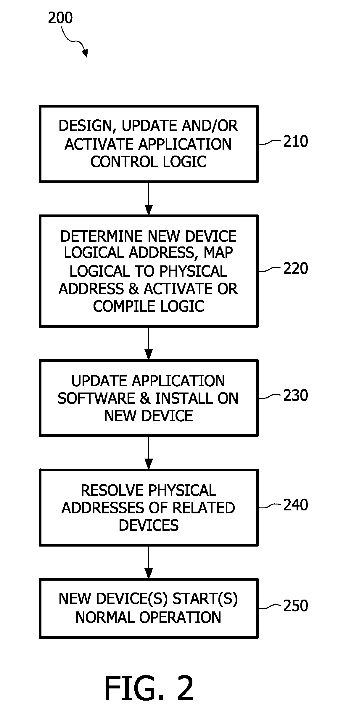
a networked control system and logical address technology, applied in the field of networked control system logical address use, can solve problems such as inflexible and more error-prone network design, complicated system design and maintenance, and unreadable by users

Active Publication Date: 2012-07-10
SIGNIFY HLDG BV
View PDF12 Cites 13 Cited by
  • Summary
  • Abstract
  • Description
  • Claims
  • Application Information

AI Technical Summary

Benefits of technology

[0011]One object of the present systems and methods is to overco

Problems solved by technology

The large number of devices in a control network, together with their small footprint and potentially very complicated application logic to be run on them, require new approaches to control network management.
However, use of physical device addresses as is currently done in conventional network systems, such as control systems (e.g. using the ZigBee™ protocol), complicates the design and maintenance of the systems.
For example, if control logic is defined using physical device addresses, then the network design, e.g. with respect to setup and maintenance procedures, becomes inflexible and more error-prone, particularly when the network is defined or setup by non-technical people.
One problem with conventional control systems is that all the physical device addresses must be known at or during the time when the control logic is being designed.
Another problem is that when a device is added once the network is up, a new or previously unknown physical address will have to be manually incorporated into the control logic.
A further problem is that of hot replacement of device in a system which often requires application and support logic re-installation on all devices hosting logic related to and / or wishing to communicate results to the replaced device.
In addition, typically, the addresses assigned to devices or groups of devices are purely numerical, and are meaningless to users, and may even be unreadable by the user.

Method used


Image

  • Networked control system using logical addresses
  • Networked control system using logical addresses
  • Networked control system using logical addresses

Examples


Embodiment Construction

[0017]The following description of certain exemplary embodiments is merely exemplary in nature and is in no way intended to limit the invention, its applications, or uses. In the following detailed description of embodiments of the present systems and methods, reference is made to the accompanying drawings which form a part hereof, and in which are shown by way of illustration specific embodiments in which the described systems and methods may be practiced. These embodiments are described in sufficient detail to enable those skilled in the art to practice the presently disclosed systems and methods, and it is to be understood that other embodiments may be utilized and that structural and logical changes may be made without departing from the spirit and scope of the present system.

[0018]The following detailed description is therefore not to be taken in a limiting sense, and the scope of the present system is defined only by the appended claims. The leading digit(s) of the reference n...


PUM


Abstract

Networked control systems and methods include a plurality of devices connected to a network. At least one device has a logical address that includes a device type and a device location in an environment of the device in a user readable and understandable format, such as English or other languages. The system further includes a processor connectable to the network and configured to execute control logic using the logical addresses. A memory is provided for storing a mapping from the logical address to a physical network address of the device.

Description

FIELD OF THE INVENTION[0001]The present invention relates to use of logical addresses for networked control systems with communication independent control logic.BACKGROUND OF THE INVENTION[0002]Networking of devices is a ubiquitous trend in business (commercial, industrial, institutional) and also consumer markets. Examples where networked devices are used include building automation systems, e.g. for lighting, heating / ventilation / cooling, and safety, where various devices like light ballasts, switches, daylight / occupancy sensors, actuators, meters etc., are inter-connected such as wirelessly via RF modules, for example. The large number of devices in a control network, together with their small footprint and potentially very complicated application logic to be run on them, require new approaches to control network management.[0003]To reduce complexity of creating or configuring networks and node addressing, various systems and methods are known for network addressing, where address...

Claims


Application Information

Patent Timeline
IPC IPC(8): H04L12/28
CPCH04L12/2807H04L29/1232H04L29/12594H04L29/12801H04L61/2092H04L61/303H04L61/6004H04L67/12H04L2012/2841H04L2012/285H04W4/029H04L61/5092H04L2101/30H04L2101/604
Inventor VAN STEEN, MARTINUS RICHARDUSVAN HERK, ROBERTVERBERKT, MARK HENRICUSERDMANN, BOZENASCHREYER, OLIVERLELKENS, ARMAND MICHEL MARIE
Owner SIGNIFY HLDG BV
Learn More