
Multi-purpose gunsmithing fixture

Active Publication Date: 2012-07-03
CASHWELL KENNETH W
View PDF10 Cites 41 Cited by
  • Summary
  • Abstract
  • Description
  • Claims
  • Application Information

AI Technical Summary

Benefits of technology

[0010]Because the bolt assembly does not have to be removed from the upper receiver in order for the upper receiver to be engaged in or on the clamshell or block style fixture, it is possible to place a loaded upper receiver (and upper receiver still having an unfired round in its chamber) within the fixture.
[0031]This invention separately provides a gunsmithing fixture that, by virtue of the requirement that the bolt and bolt assembly be removed from the upper receiver prior to use of the fixture, is inherently safer than known gunsmithing fixtures.

Problems solved by technology

Unfortunately, the known gunsmithing fixtures suffer from a number of drawbacks.
Because the clamshell style fixture surrounds the outside of the upper receiver, the external working portions of the upper receiver cannot be accessed when the clamshell fixture is used.
Because the block style fixture only secures the upper receiver by the upper receiver lugs, the amount of torque cannot be placed on the upper receiver without the danger of fracturing the lugs of the upper receiver and / or damaging the fixture itself.

Method used


Image

  • Multi-purpose gunsmithing fixture
  • Multi-purpose gunsmithing fixture
  • Multi-purpose gunsmithing fixture

Examples


Embodiment Construction

[0057]For simplicity and clarification, the design factors and operating principles of the gunsmithing fixture of this invention are explained with reference to various exemplary embodiments of a gunsmithing fixture according to this invention. The basic explanation of the design factors and operating principles of the gunsmithing fixture is applicable for the understanding, design, and use of the gunsmithing fixture of this invention.

[0058]It should be appreciated that the terms “gunsmithing fixture” and “upper receiver” are used for basic explanation and understanding of the systems, methods, and / or apparatuses of this invention. Therefore, the terms “gunsmithing fixture” and “upper receiver” are not to be construed as limiting the systems, methods, and apparatuses of this invention.

[0059]It should also be appreciated that while the various exemplary embodiments of the present invention are described and shown as being utilized in connection with the upper receiver of an AR15 / M16,...


PUM


Abstract

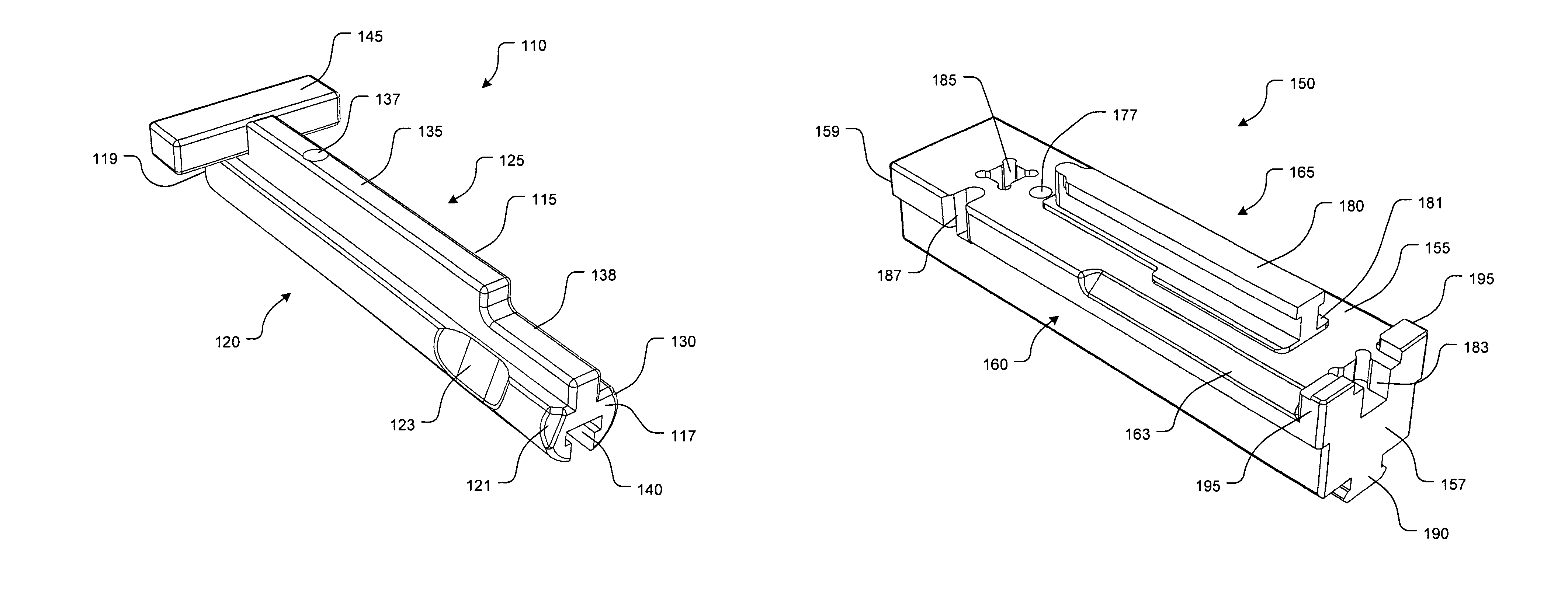
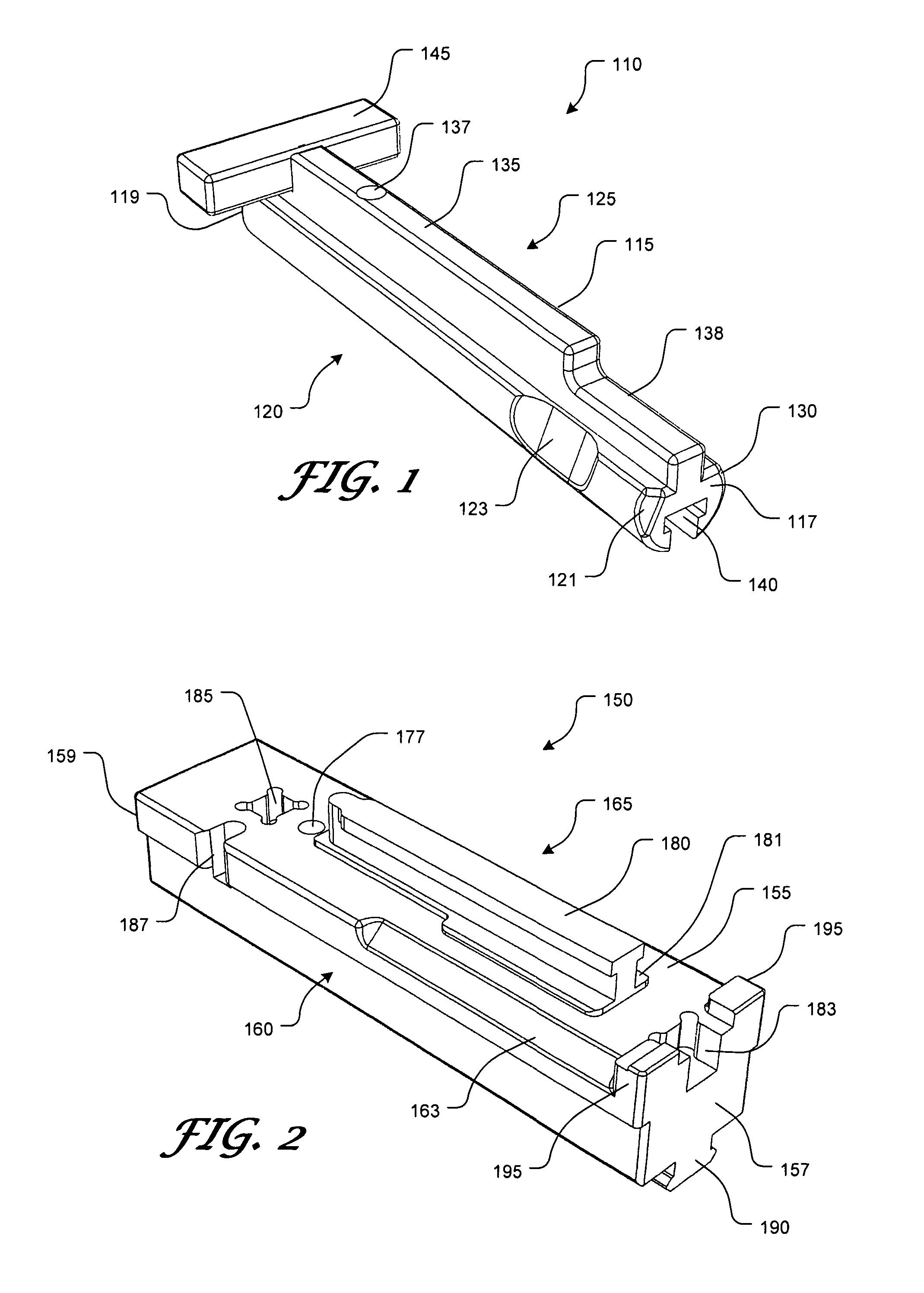
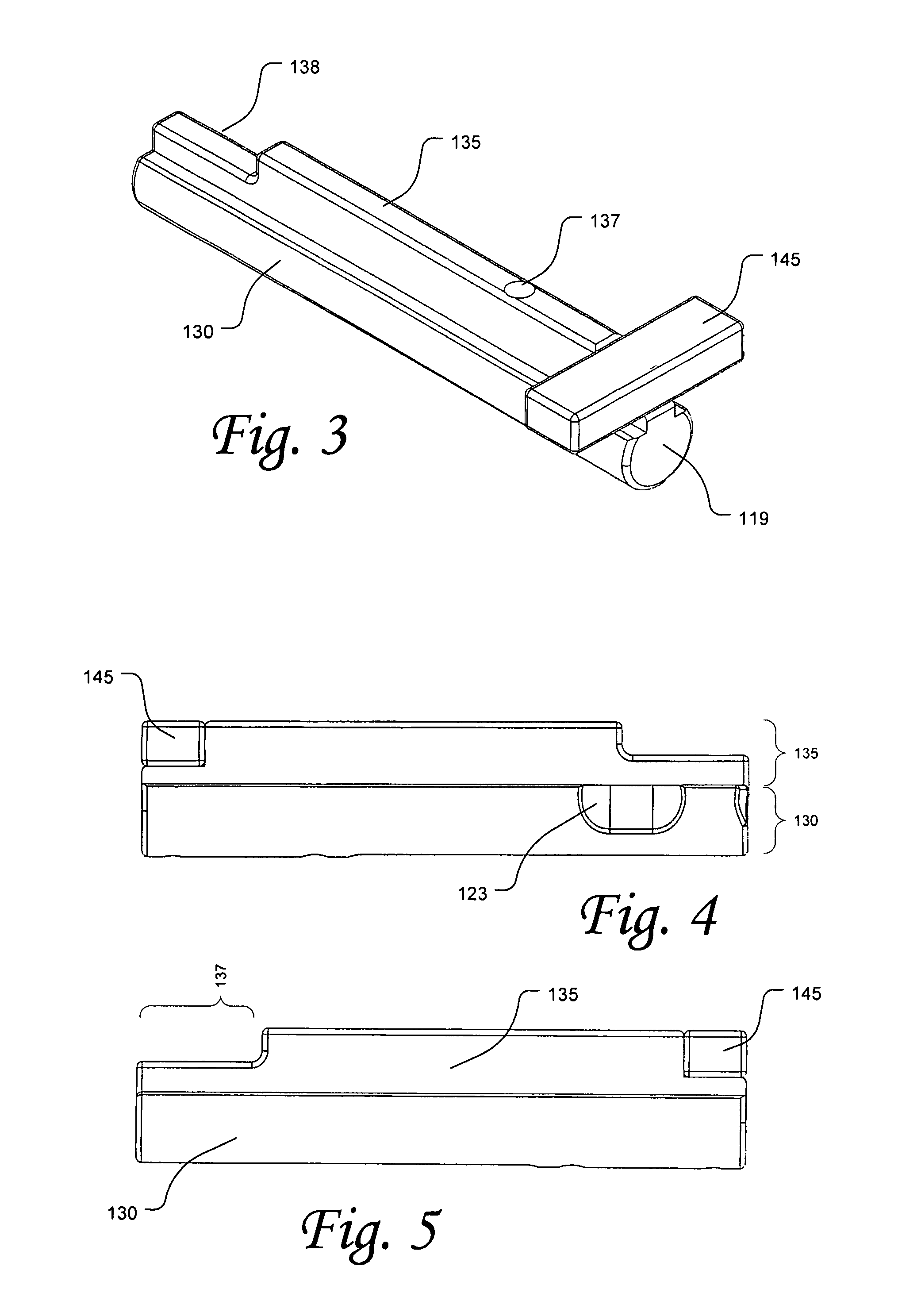
A gunsmithing fixture for use with an upper receiver, including an upper portion having an upper body portion, wherein the upper body portion comprises a partially cylindrical portion and a rib portion, and wherein the upper body portion includes a groove formed along the central longitudinal axis of at least a portion of the upper body portion; and a lower portion having a lower body portion, wherein the lower body portion includes a protrusion extending from at least a portion of the lower body portion, wherein the lower body portion comprises a front receiver lug recess and a rear receiver lug recess; wherein the groove of the upper body portion is formed so as to slidably mate with the protrusion of the lower portion, such that the upper body portion can be secured to the lower body portion via slidable interaction of the groove and the protrusion.

Description

CROSS-REFERENCE TO RELATED APPLICATIONS[0001]This application claims the benefit of U.S. Provisional Patent Application Ser. No. 61 / 204,762, filed Jan. 9, 2009, the entire disclosure of which is incorporated herein by reference.BACKGROUND OF THE INVENTION[0002]1. Field of the Invention[0003]This invention relates generally to gunsmithing fixtures. In particular, the present invention relates to a multi-purpose gunsmithing fixture to aid in the proper and efficient assembly and / or modification of an AR15 / M16 style upper receiver.[0004]2. Description of Related Art[0005]When assembling, repairing, or performing maintenance on the upper receiver of an AR15 / M16 style rifle, it is important that the upper receiver be held firmly in place. The upper receiver is placed in a gunsmithing fixture while assembly, maintenance, or repair work is done on the upper receiver or its components. Typically, the fixture is then clamped into a standard bench vise.[0006]Known gunsmithing fixtures for use...

Claims


Application Information

Patent Timeline
IPC IPC(8): F41A23/18F41C27/00B25B11/00B23Q3/18
CPCF41A23/18F41A35/00F41C27/00
Inventor CASHWELL, KENNETH W.
Owner CASHWELL KENNETH W
Learn More