
Electronic racquet stringing machine

a stringing machine and electronic technology, applied in the field of racket stringing machines, can solve the problems of limited resolution and frequent calibration

Active Publication Date: 2012-06-26
MARTINEZ DANILO
View PDF21 Cites 10 Cited by
  • Summary
  • Abstract
  • Description
  • Claims
  • Application Information

AI Technical Summary

Benefits of technology

"The present invention relates to a new stringing machine for rackets that uses an electronic controller to measure and control the tension on the string. The machine has a tension head that uses a spring-loaded vise to compress a helical spring, which is then driven by a chain drive to compress the bias spring. The machine can read the tension on the racket directly, resulting in more accurate tensioning. The machine is portable, durable, and easy to repair. It has a display circuit, keypad, and microprocessor circuit to control the tensioning process. The invention provides a more efficient and precise method for stringing rackets."

Problems solved by technology

Modified, Held's device is still used universally although its accuracy is often called into question, its resolution is limited, and it needs frequent calibration.
This Constant Pull feature is often the cause of undesirable results.

Method used


Image

  • Electronic racquet stringing machine
  • Electronic racquet stringing machine
  • Electronic racquet stringing machine

Examples


Embodiment Construction

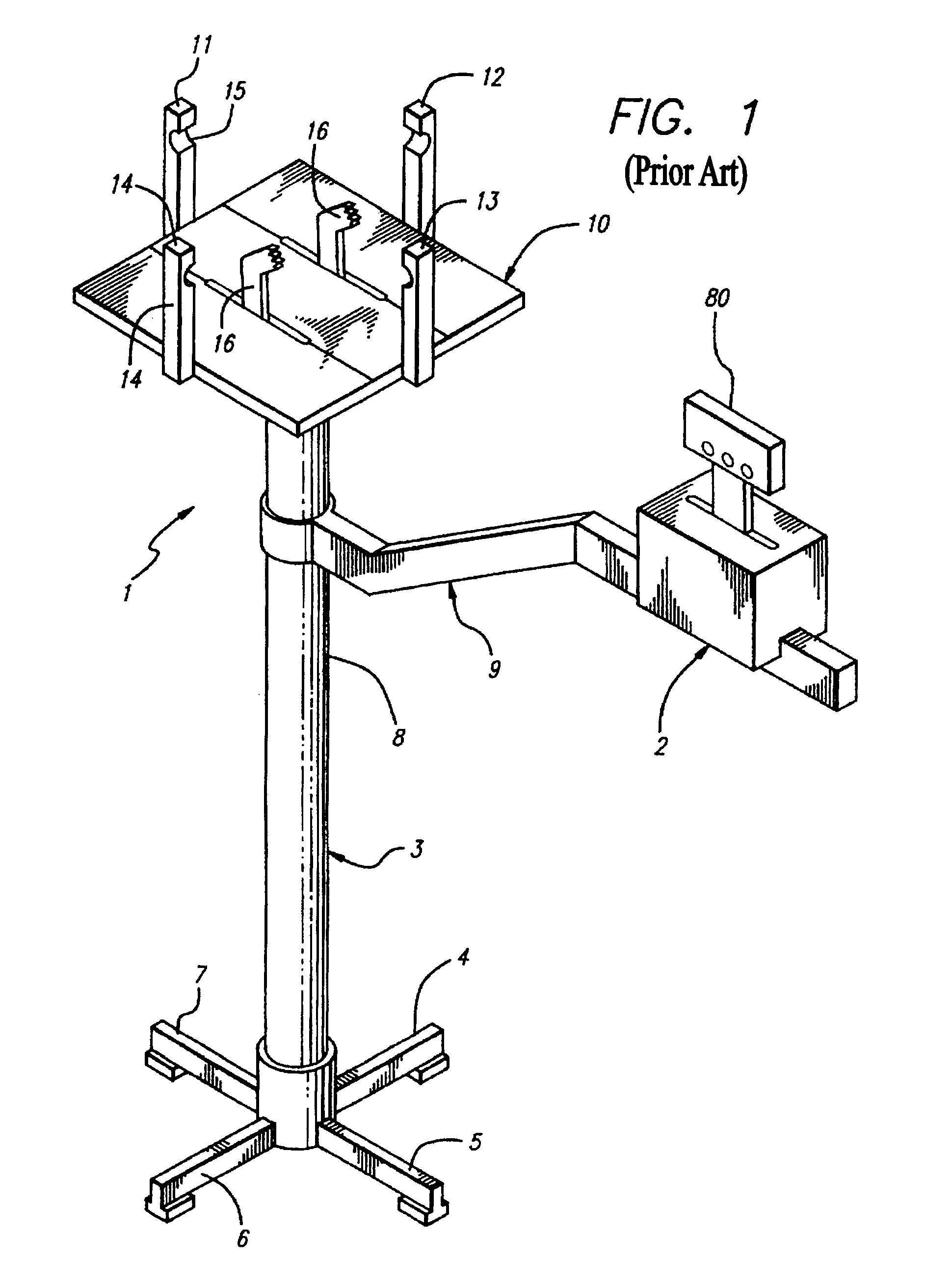
[0034]FIG. 1 is a view of applicant's stringing machine with its two major components, the racket cradle assembly 1 and the tension head assembly 2. The stringing machine has a base 3 including legs 4, 5, 6 and 7 spaced from each other at 90 degrees. The base also includes a vertical support column 8, on top of which is fitted the racket cradle assembly tension bar 9. Mounted on the support column and above the tension bar is the racket cradle assembly which takes the form of a turntable. Both the tension bar and the racket cradle assembly pivot on the support column so that when a racket is mounted onto the cradle, as we will see, the string can be aligned from the point it leaves the racket frame to where it enters the snatch vise 80.

[0035]The racket cradle assembly platen 10 has two functions; to support four movable posts or fixing elements 11, 12, 13 and 14 that are placed at the top, bottom and two sides of the racket and ensure the horizontal clamping in position of the tenni...


PUM


Abstract

A tension head for a racquet stringing machine in which roller bearings are used between the outer vice plates and the vice jaws. Also, a pin on one vice jaw extends into a slot in an outer vice plate and in the slot is an adjustable screw which allows override of the compression on string upon contact with the pin. Also a follower is mounted on the lead screw and steadied by a guide bar in order to reduce spurious movement of the snatch vice during operation.

Description

FIELD OF INVENTION[0001]The present invention relates to racket stringing machines.RELATED PATENTS[0002]U.S. Pat. Nos. 5,733,212 and 6,227,990 are related to this inventionTHE PRIOR ART[0003]Many machines have been devised for stringing and restringing game rackets, such as those used for tennis, badminton, squash and the like.[0004]After 1969, a process that had previously been done by guess, intuition or the displacement of fixed weights (Serrano, U.S. Pat. No. 2,188,250) became more efficient and precise by using the compression of a spring with its inherent linearity (Held, U.S. Pat. No. 3,441,275) as a comparator. Here the stringing machine (FIG. 15) holds the racket in a cradle in a position parallel to the ground 130. The person stringing a racket threads the string through a hole in the racket frame, attaching one end to the racket and the other to an external self-tightening vise 131 (snatch vise). The vise is part of a hand cranked tensioning assembly 132 (tension head) th...

Claims


Application Information

Patent Timeline
Patent Type & Authority Patents(United States)
IPC IPC(8): A63B51/14
CPCA63B51/14A63B2243/0075A63B2243/0083A63B2243/0087A63B2102/06A63B2102/02A63B2102/04A63B51/16
Inventor WISE, HERBERT H.
Owner MARTINEZ DANILO
Learn More