Stationary blade ring of axial compressor
a compressor and blade technology, applied in the direction of machines/engines, stators, liquid fuel engines, etc., can solve the problems of low damping effect in response to blade vibration, possibility of cracking starting in the fillet weld zone, notch defect in the bottom of a welded overlay, etc., to enhance the reliability of the compressor, eliminate the possibility of cracking, and prolong the interval between periodic inspections
- Summary
- Abstract
- Description
- Claims
- Application Information
AI Technical Summary
Benefits of technology
Problems solved by technology
Method used
Image
Examples
embodiment 1
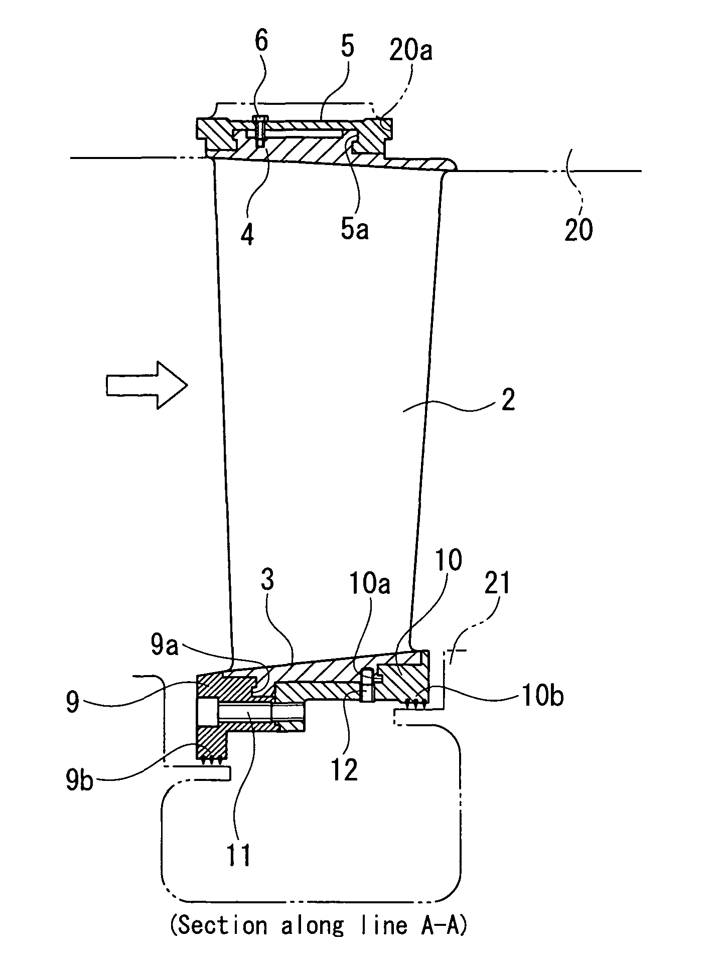
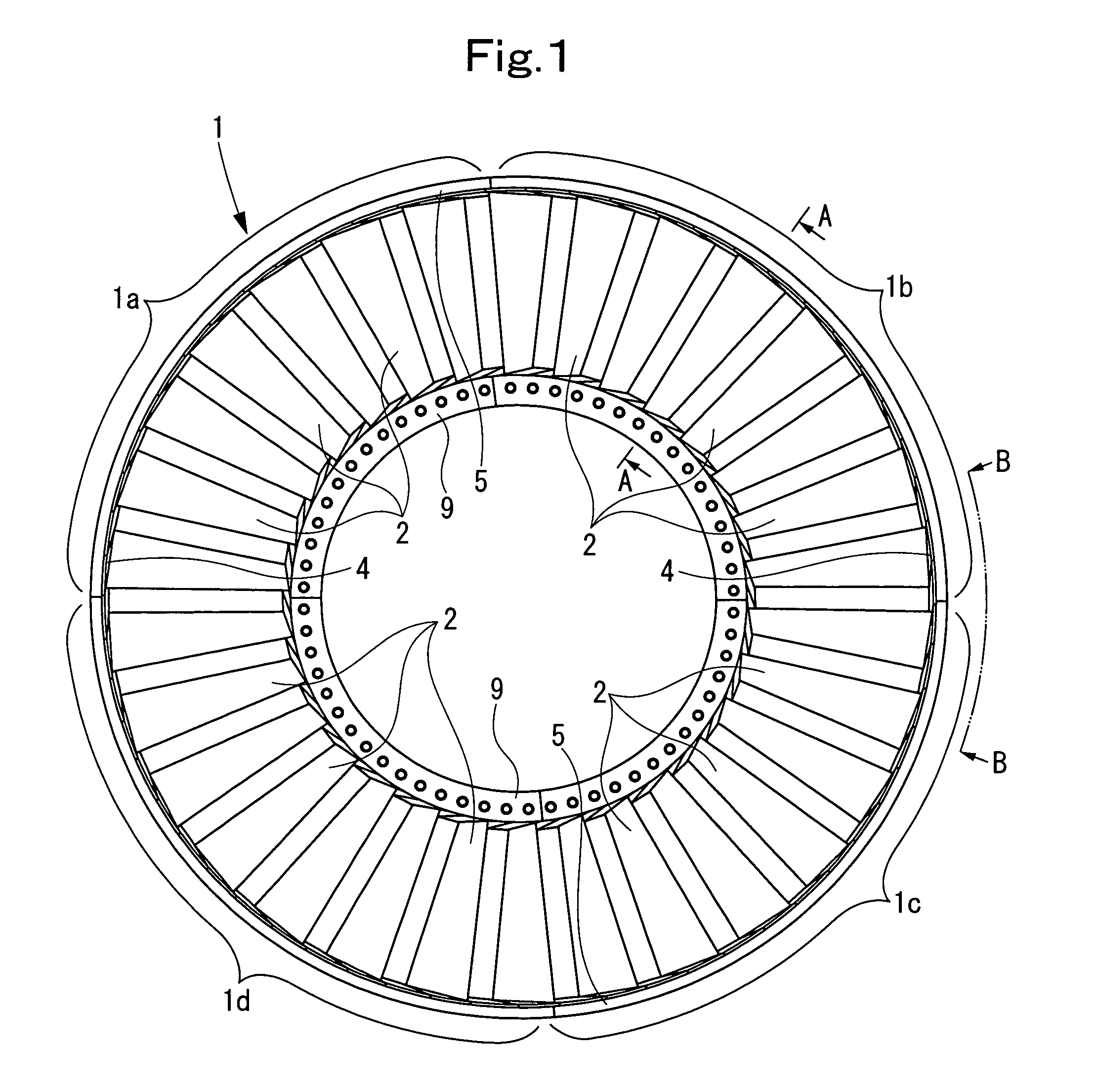
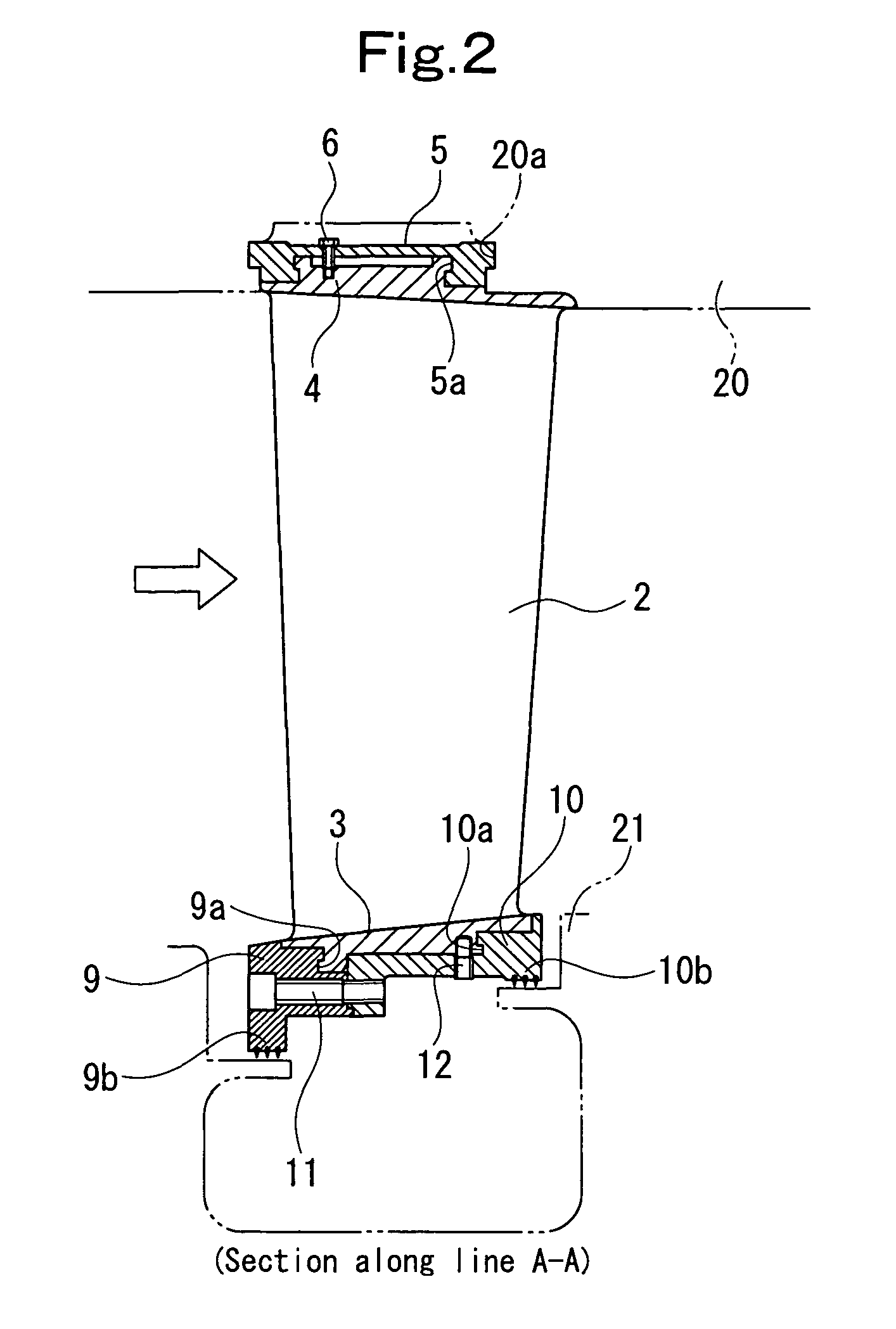
[0029]FIG. 1 is a front view of a compressor stationary blade ring of a gas turbine, showing Embodiment 1 of the present invention. FIG. 2 is a sectional view taken on line A-A in FIG. 1. FIG. 3 is a view taken along line B-B in FIG. 1.
[0030]As shown in FIG. 1, a compressor stationary blade ring 1 of a gas turbine according to the present embodiment is divided into first to fourth units, 1a to 1d, in the circumferential direction. The first unit 1a is equipped with seven stationary blades 2, the second unit 1b is equipped with eight stationary blades 2, the third unit 1c is equipped with seven stationary blades 2, and the fourth unit 1d is equipped with eight stationary blades 2. The first unit 1a and the second unit 1b are built into an upper half of a compressor casing 20 (see FIG. 2), while the third unit 1c and the fourth unit 1d are built into a lower half of the compressor casing 20.
[0031]The structures of the first unit 1a to the fourth unit 1d will be described with referenc...
embodiment 2
[0042]FIG. 4 is an exploded perspective view of essential parts of the compressor stationary blade ring of the gas turbine, showing Embodiment 2 of the present invention. FIG. 5 is an enlarged sectional view of the essential parts in FIG. 4.
[0043]This is an embodiment in which the outer shroud portion 4 and the spacer 8 in Embodiment 1 are coupled together by a narrow band member 5A (coupling means) fitted into dovetail grooves 4a (the dovetail groove of the spacer 8 is not shown) formed in upper surface regions (on the outer peripheral side) of the outer shroud portion 4 and the spacer 8, and the outer shroud portion 4 and the spacer 8 are directly slidably fitted into the guide groove portion 20a of the compressor casing 20. Other features are the same as those in Embodiment 1.
[0044]According to this embodiment, the advantage is obtained that the band member 5A can be formed compactly, in addition to the same actions and effects as those in Embodiment 1. In the present embodiment ...
embodiment 3
[0045]FIG. 6 is a sectional view of the essential parts of the compressor stationary blade ring of the gas turbine, showing Embodiment 3 of the present invention.
[0046]This is an embodiment in which the outer shroud portions 4 (and spacers 8) in Embodiment 1 are coupled together by a narrow auxiliary band member 7 different from the band member 5 before they are coupled together by the band member 5. Other features are the same as those in Embodiment 1.
[0047]According to this embodiment, in addition to the same actions and effects as those in Embodiment 1, there is the advantage that the stationary blades 2 are not separated from each other even when the band member 5 is detached during a dismounting operation for inspection or the like.
PUM
 Abstract
Description
Claims
Application Information
 - R&D
- Intellectual Property
- Life Sciences
- Materials
- Tech Scout
- Unparalleled Data Quality
- Higher Quality Content
- 60% Fewer Hallucinations
Browse by: Latest US Patents, China's latest patents, Technical Efficacy Thesaurus, Application Domain, Technology Topic, Popular Technical Reports.
© 2025 PatSnap. All rights reserved.Legal|Privacy policy|Modern Slavery Act Transparency Statement|Sitemap|About US| Contact US: help@patsnap.com


