
Data storage apparatus

a data storage and apparatus technology, applied in the field of data storage apparatuses, can solve the problems of ineffective cooling of disk drives, no longer constrained airflow, and lack of flexibility in the arrangement of disk drives within data storage units, and achieve the effect of horizontal spacing

Active Publication Date: 2012-06-05
STORCENTRIC DIP LENDER LLC
View PDF41 Cites 52 Cited by
  • Summary
  • Abstract
  • Description
  • Claims
  • Application Information

AI Technical Summary

Benefits of technology

[0012]According to a third aspect of the present invention, there is provided apparatus for storing data and supplying stored data, said apparatus comprising: a main housing; an electric power supply located within said main housing; a panel located within said main housing, said panel supporting a plurality of electric connectors for connecting said power supply to other component parts of said apparatus; a plurality of units, each said unit comprising a plurality of data storage elements, each said unit being mounted to slide within said main housing such that each one of said units is slidable from out of said main housing to provide access to said data storage elements of said unit, and a plurality of cable modules, each module comprising a cable having a first connector at a first end configured to connect to one of said units and a second connector at a second end configured to connect with one of said electric connectors supported by said panel, and a moveable rigid structure supporting said second connector and providing a barrier preventing manual access to said panel thereby allowing said second connector to be disconnected by manually moving said rigid structure.

Problems solved by technology

A first problem with such a data storage unit relates to a fan that is arranged to provide a flow of cooling air over the disk drives.
However, if one of the support structures is withdrawn from the outer main housing, for example to replace a defective disk drive, the airflow is no longer constrained and cooling of the disk drives becomes less effective.
A further problem with known data storage units that has been identified by the Applicant, relates to a lack of flexibility in the arrangement of disk drives within a data storage unit.
For example, if a data storage unit having a particular number of disk drives of a particular type is being used, then the options for upgrading the storage capacity and / or performance of the unit are limited.
Consequently, a unit may be purchased that soon becomes inadequate and requires replacing.

Method used


Image

  • Data storage apparatus
  • Data storage apparatus
  • Data storage apparatus

Examples


Embodiment Construction

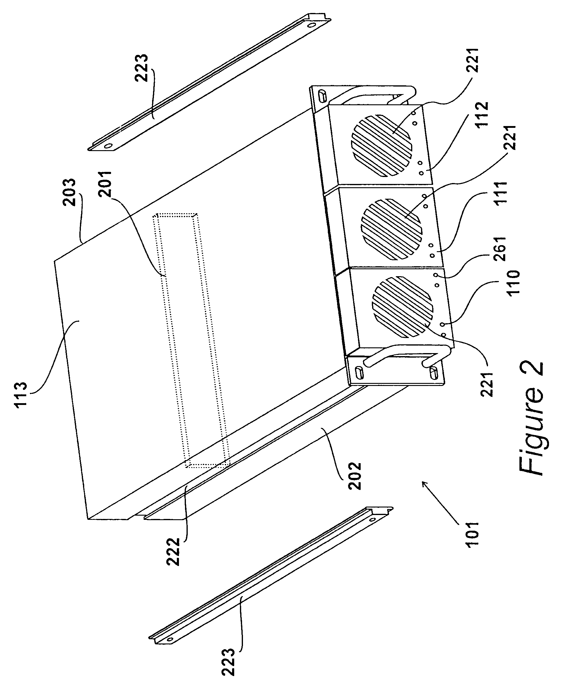
FIG. 1

[0033]A data storage unit 101 embodying the present invention is shown mounted in a rack 102 in FIG. 1.

[0034]The rack 102 is built in accordance with an international standard, EIA-310, and therefore has a specified depth from the front panel 103 to the back panel 104. Similarly, the rack 102 has a standard sized gap between a first rail 105 and a second rail 106 which form part of the front panel 103 and are provided with holes 107 allowing equipment such as data storage unit 101 to be attached and supported.

[0035]The data storage unit 101 has a generally rectangular form, but includes a mounting plate 108 at its front end that is provided with apertures allowing the data storage unit to be attached to the rails 105 and 106 of the rack 102. Most of the data storage unit 101 has a width configured to allow said unit to pass between the rails 105 and 106 of the rack 102, and a depth that ensures a gap is provided between the rear end 109 of the data storage unit 101 and the bac...


PUM


Abstract

Apparatus for storing data and supplying stored data comprising a main housing containing control circuitry for controlling signals to a plurality of disk drives. The main housing has a plurality of mounting mechanisms each configured to support a unit of a first type. The apparatus further comprises a plurality of cables each having a first connector for connecting to a unit of the first type for providing signals from the control circuitry. The apparatus has a first unit, of a first type, having a plurality of second connectors each connected to a disk drive and a fan providing a flow of air for cooling the disk drives and the control circuitry. The first unit is connected to a first one of the cables and mounted in a first one of the mounting mechanisms such that the first unit is mounted to slide into the main housing. The apparatus also has a second unit, of a second type, supported by a second one of the mounting mechanisms and mounted to slide into the main housing. The second unit is connected to a second one of the cables and has a fan providing a flow of air for cooling the control circuitry. The second unit is removable from the main housing and replaceable by a unit of the first type.

Description

BACKGROUND OF THE INVENTION[0001]1. Field of the Invention[0002]The present invention relates to apparatus for storing data and supplying stored data.[0003]2. Description of the Related Art[0004]Data storage units are known that are configured for mass data storage or as RAID (redundant array of inexpensive disks) systems. Such storage units comprise of several disk drives and one or more control units for controlling data input to, and output from, the disk drives. The storage units may be located within a standard size rack unit, typically occupying 1 U to 6 U (1 to 6 rack units) of rack space, and may share the rack with other equipment, and possibly other such data storage units.[0005]Occasionally it is necessary to access the disk drives, for example, for the purposes of replacement of a defective drive, or a drive needing to be upgraded. In some data storage units, access to the disk drives is made possible by the removal of a panel that forms part of the outer main housing of...

Claims


Application Information

Patent Timeline
Patent Type & Authority Patents(United States)
IPC IPC(8): H05K7/14
CPCG11B33/02G11B33/126H02G11/00G11B33/142G11B33/128
Inventor JEFFERY, ALANRANDALL, ANDREW PAUL GEORGEBELCHER, DAVID IANBRYERS, ALASTAIRFREEMAN, STEPHEN
Owner STORCENTRIC DIP LENDER LLC
Learn More