
Adjusting method of flash intensity

a technology of flash intensity and adjustment method, which is applied in the field of adjusting the luminance of flash lamps, can solve the problems of insufficient exposure of main flash lights, excessive flash intensity of flash lights, and image corresponding, and achieve the effect of reducing the luminance error of digital images

Inactive Publication Date: 2012-05-29
ALTEK CORP
View PDF6 Cites 5 Cited by
  • Summary
  • Abstract
  • Description
  • Claims
  • Application Information

AI Technical Summary

Benefits of technology

This method ensures the digital image capture apparatus produces a main-flash light with the correct intensity in any shooting mode, reducing luminance errors caused by user setting mistakes and achieving balanced exposure.

Problems solved by technology

When the digital image capture apparatus is close to the object to be shot, if the normal mode is set, the image corresponding to the object and retrieved under the main-flash light has an over exposure since the excessive high flash intensity of the pre-flash light causes the main-flash light to have an excessive high flash intensity.
When the digital image capture apparatus is far away from the object to be shot, if a macro mode is set, the image corresponding to the object and retrieved under the main-flash light has an insufficient exposure since the excessive low flash intensity of the pre-flash light causes the main-flash light to have an excessive low flash intensity.
However, a user may not always switch to a corresponding shoot mode as the actual circumstance requires.
If a pre-flash is carried out by a pre-flash light with an incorrect flash intensity, the flash intensity of the main-flash light evaluated by the digital image capture apparatus may become inaccurate accordingly.

Method used


Image

  • Adjusting method of flash intensity
  • Adjusting method of flash intensity
  • Adjusting method of flash intensity

Examples


Embodiment Construction

[0032]The detailed features and advantages of the present invention described hereinafter are sufficient for those of ordinary skill in the art to appreciate the technical content of the present invention and implement the present invention accordingly, and from the content, claims, and figures disclosed in this specification, those of ordinary skill in the art can easily understand the objectives and advantages of the present invention.

[0033]The adjusting method of flash intensity according to the present invention is applied to a digital image capture apparatus with a flash lamp. The method of the present invention may be in-built in a storage device of the digital image capture apparatus through software or firmware program, and the in-built software or firmware program is then executed by a processor of the digital image capture apparatus to realize the adjusting method of flash intensity according to the present invention. Herein, the digital image capture apparatus may be a di...


PUM


Abstract

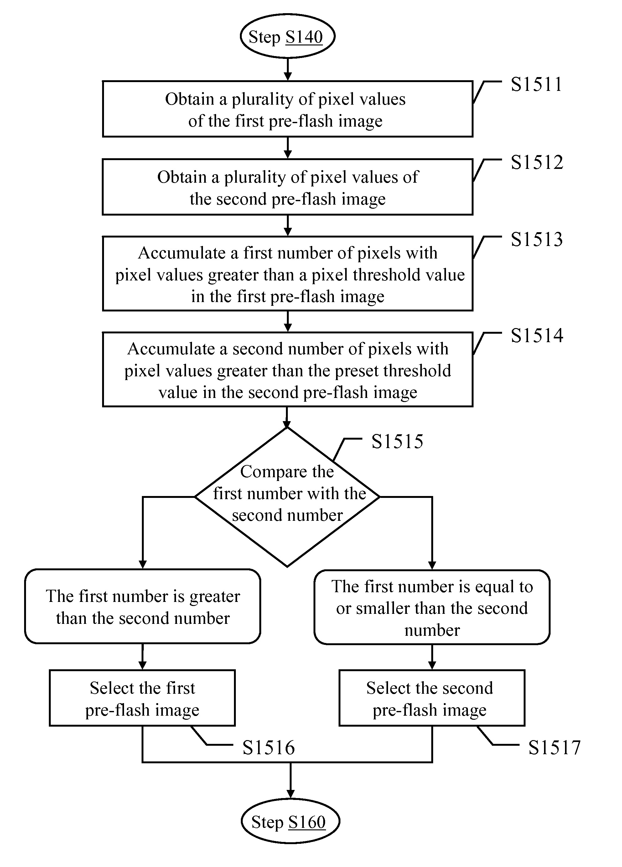
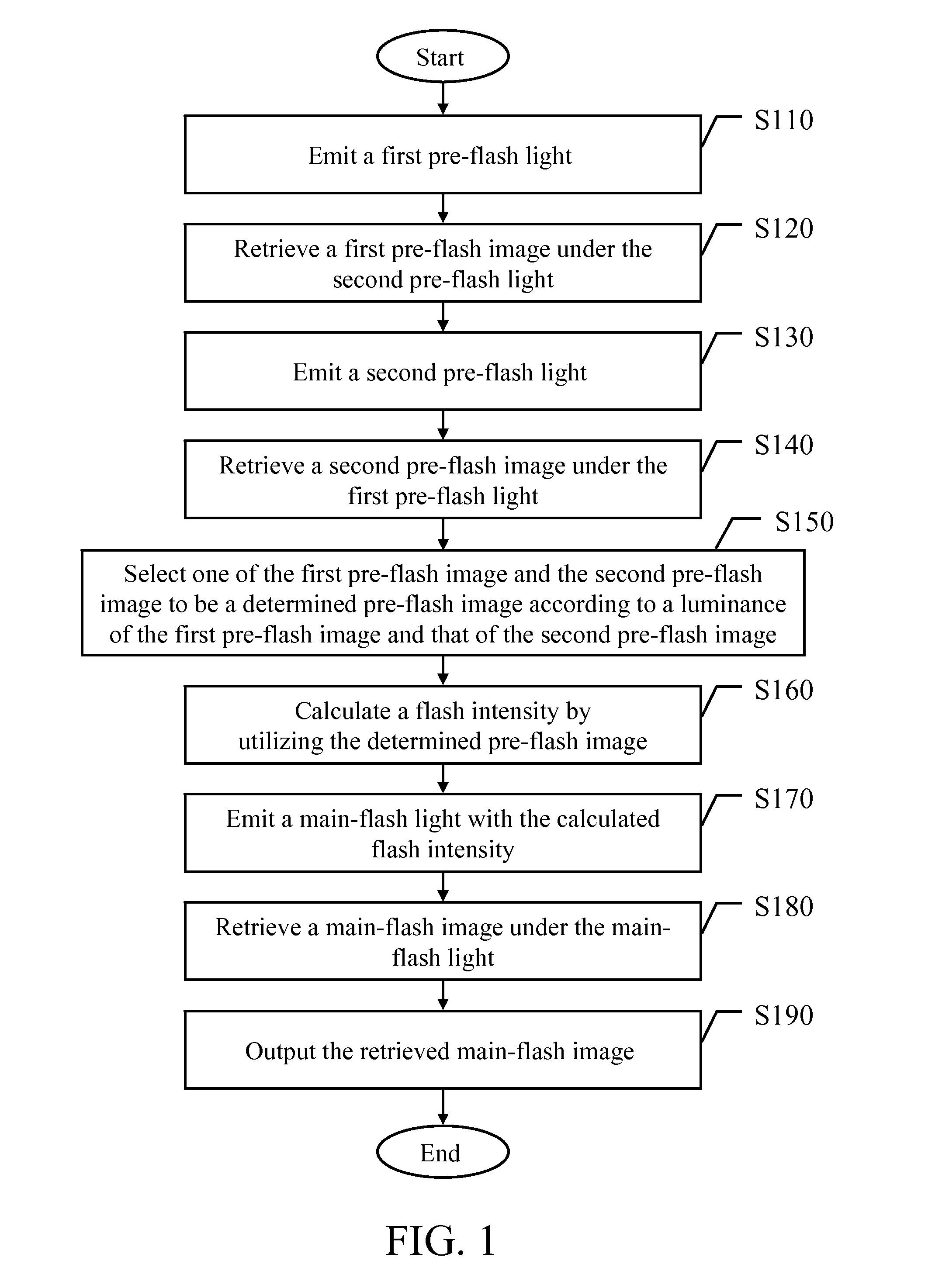
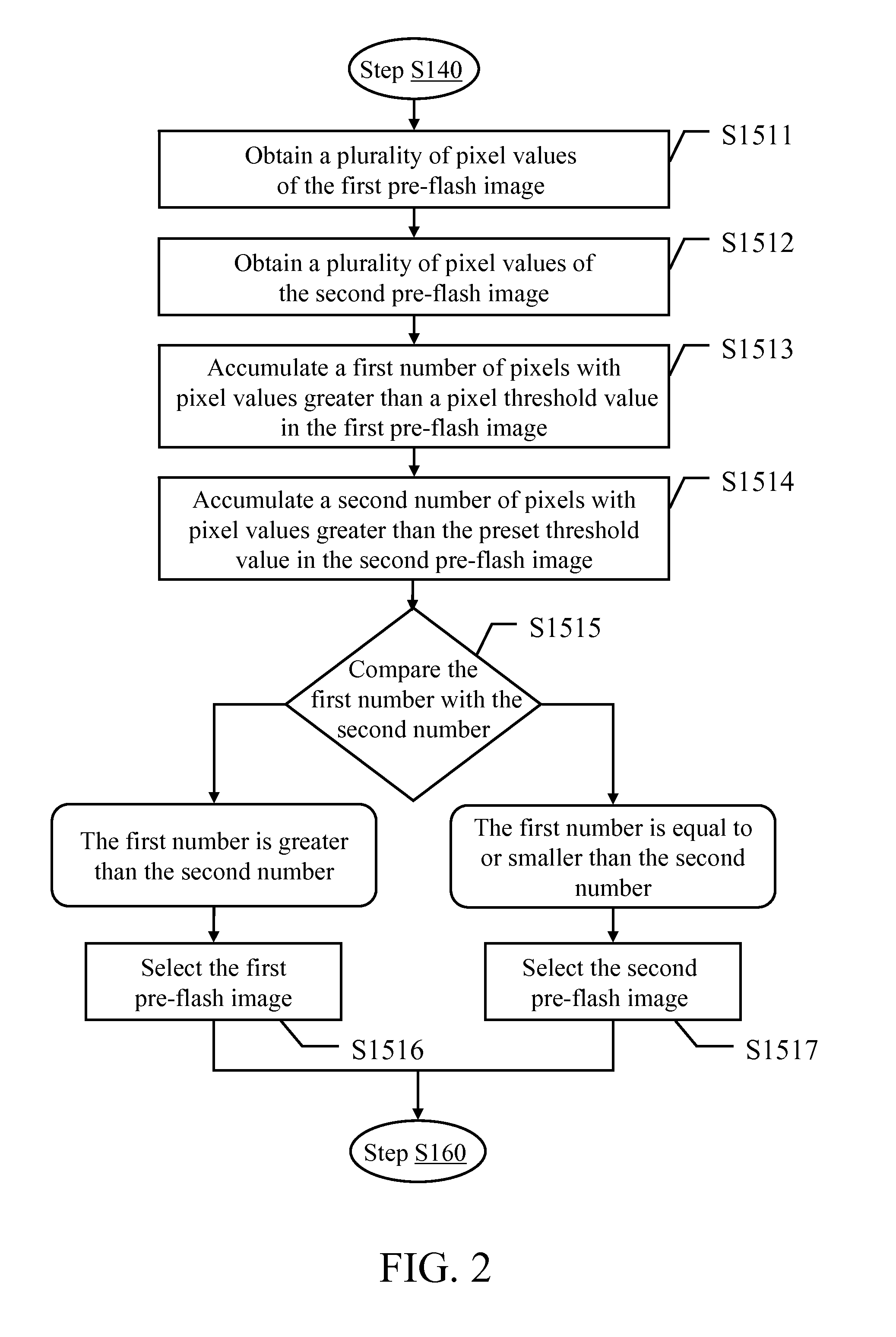
An adjusting method of flash intensity is applied in an image capture apparatus with a flash lamp, where two pre-flash images corresponding the object are retrieved under two different pre-flash lights, respectively, and then a flash intensity of main-flash light is calculated according to one of the retrieved pre-flash images, so as to retrieve a main-flash image corresponding the object under the main-flash light with the calculated main-flash light.

Description

CROSS-REFERENCE TO RELATED APPLICATIONS[0001]This non-provisional application claims priority under 35 U.S.C. §119(a) on Patent Application No(s). 097151802 filed in Taiwan, R.O.C. on Dec. 31, 2008 the entire contents of which are hereby incorporated by reference.BACKGROUND[0002]1. Field of the Invention[0003]The present invention relates to a method for adjusting an image pickup luminance, and in particular, to an adjusting method of flash intensity for a flash lamp.[0004]2. Related Art[0005]A flash lamp is disposed in a digital image capture apparatus to compensate for an insufficient luminance for an object to be shot during shooting. In other words, when the object to be shot is in an environment with a low luminance, the digital image capture apparatus triggers the flash lamp during shooting, so as to enable the luminance of a shot digital image corresponding to the object to achieve a desirable value through a strong flash light emitted by the flash lamp.[0006]Generally, the d...

Claims


Application Information

Patent Timeline
Patent Type & Authority Patents(United States)
IPC IPC(8): H04N5/222H04N5/238H04N23/75
CPCG03B13/32H04N5/2354H04N23/74
Inventor CHOU, CHAN-MINLU, CHUNG-PIN
Owner ALTEK CORP
Learn More