
Method and apparatus for coding and linking electrical appliances for control and status report

Active Publication Date: 2012-05-01
ELBEX VIDEO LTD
View PDF18 Cites 167 Cited by
  • Summary
  • Abstract
  • Description
  • Claims
  • Application Information

AI Technical Summary

Benefits of technology

[0020]The need to electrically insulate the signal cables from the power lines, elements and devices that feed AC and / or DC power to appliances, including power switches, light dimmers, AC outlets, AC socket and other AC and / or DC power devices is an absolute must and a major obstacle in mixing or mingling low voltage control wires with power wires and devices. Such mingling is prohibited by the building and the electrical codes and the use of lightguides, being a non flammable perfect insulator, is yet another major advantage of the present invention and the referenced pending applications.

Problems solved by technology

The current state of residence, home and office automation is a stagnation and difficulties.
Despite all this, the many attempts to move ahead with home automation do not seem to be successful.
The major difficulties involved with the electrical systems in premises and with the electrical and A / V appliances are far from being solved, the issues are:
This by itself prevents the use of a simple automation control standard for all currently produced appliances.
It mandates custom designs and complicated integration and / or the introduction of universal remote controls, that are non friendly and are complicated to set and operate, and are one of the sources for frustration, incompatibility and operational errors.
Other limitations with IR remote control are the line of sight and control distance, wherein the practical limit for currently produced IR remote controls is 3 meters in line of sight, with a maximum control distance is between 5˜7 meters from the appliance.
The approvals for electrical devices covering each and every electrical element and material are costly and time consuming.
The many introductions of wireless RF control, attempted time and again, are too complicated to integrate into automation systems and repeatedly failed.
The control via the AC lines is troublesome and it offers no solution for the future, it is another failed concept as well.
IR is used for most of the appliances and must be included in residence automation, but as stated above, because of the non compatibility and the line of sight limitations, the IR is not trouble free.
Other major obstacles impeding the automation systems for residence, home, offices, business and other work places or public premises are the lack of coding and addressing concept for the wiring devices and elements such as AC light switches and the AC outlets, plugs and sockets.
The above explained incompatibility of the different signaling, commands, protocols and systems, including the inherent drawback with the unique addresses allotted to each individual manufacturer of A / V and electrical appliances and the manufacturers use of non compatible code for each of the functions.

Method used


Image

  • Method and apparatus for coding and linking electrical appliances for control and status report
  • Method and apparatus for coding and linking electrical appliances for control and status report
  • Method and apparatus for coding and linking electrical appliances for control and status report

Examples


Embodiment Construction

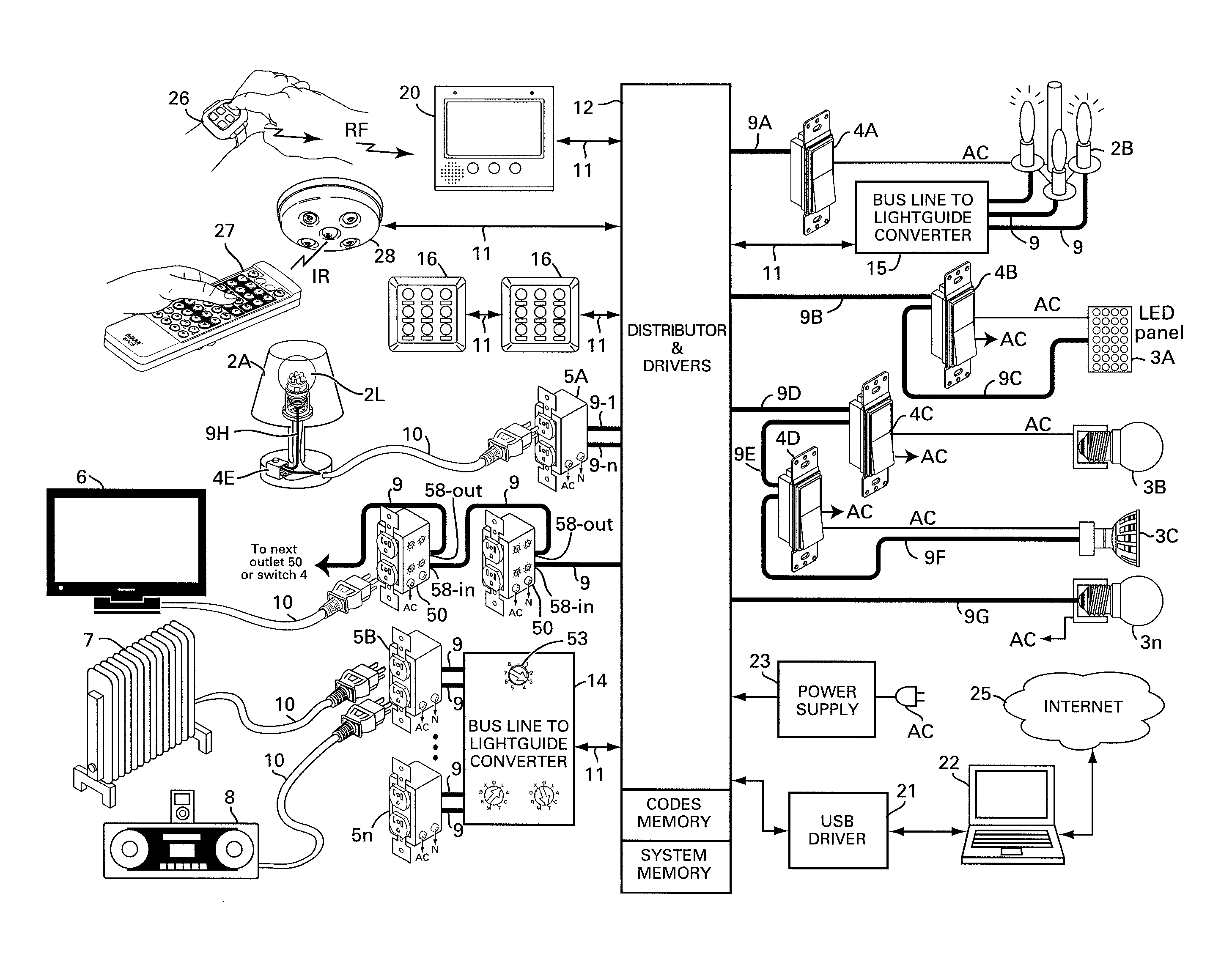
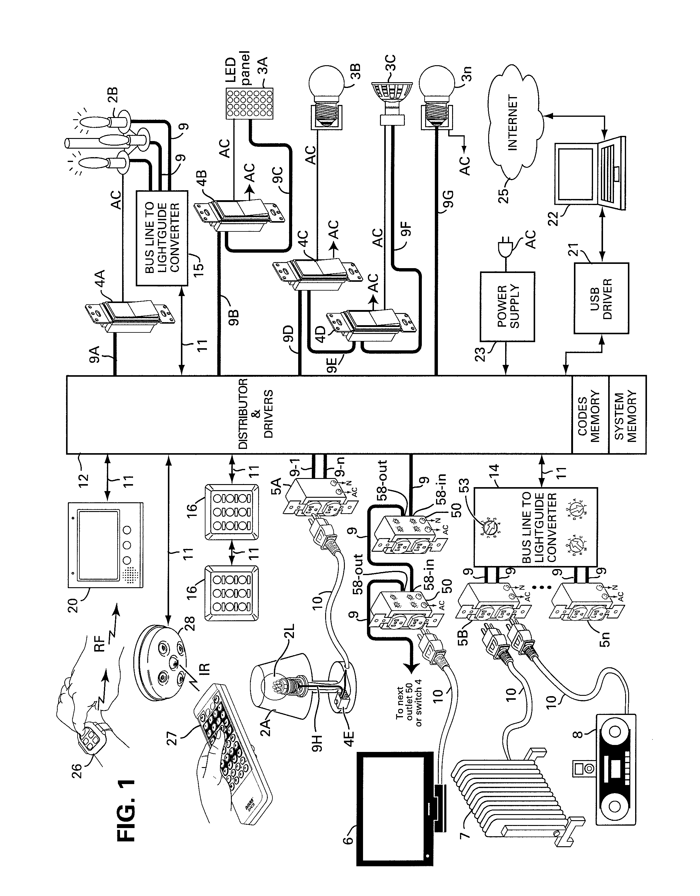
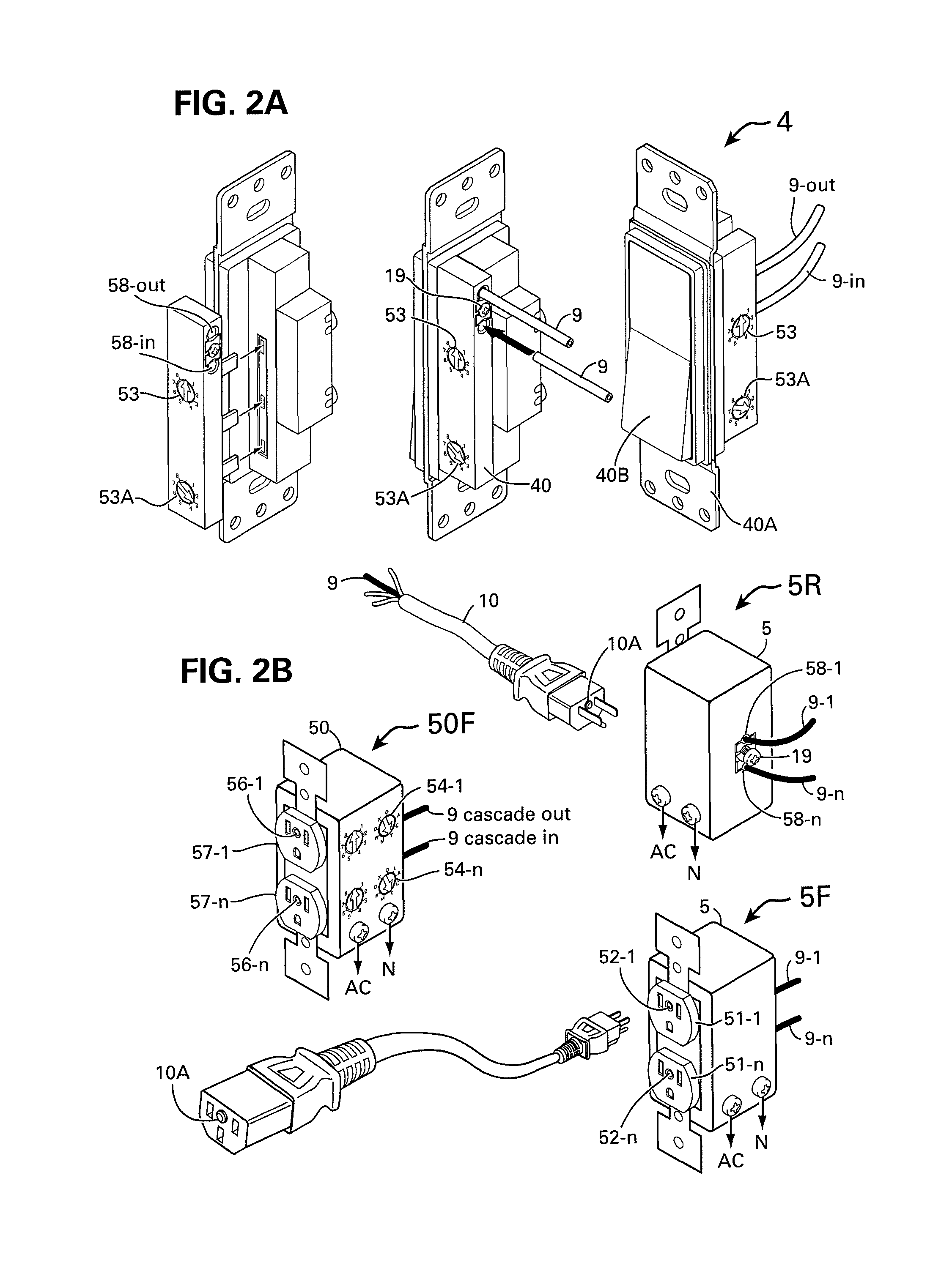
[0087]FIG. 1 shows a basic automation system for residences or other premises, wherein the appliances such as a television 6, a space heater 7, an iPod player 8, a table top lamp 2A, a chandelier 2B and four LED illuminators 3A, 3B, 3C and 3n are AC powered and are controlled and operated via lightguide or fiber optic cable 9. The shown table top lamp 2A, the television 6, the space heater 7 and the iPod player 8 are connected to the AC outlets 5 and 50 via power cable assembly 10 or 10Y that includes the lightguide 9 as shown in FIG. 2B. The AC outlets 5 and 50 with lightguide accesses or optoports are also shown in FIG. 2B.

[0088]The power switches 4A, 4B, 4C, 4D and 4E are all connected to AC power line, similar to the switch shown in FIG. 2A, and to lighting appliances, i.e., to the chandelier 2B, the table top lamp 2A, the LED panel 3A and to the LED light bulbs 3B and 3C. Each shown switch 4 is differently connected, to demonstrate the many options and variations possible when ...


PUM


Abstract

A coding method and apparatus for linking electrical appliances for control and status reporting by arbitrarily appending the appliances remote control protocol with the premise's room / zone code for identifying the appliance location and ID-code to operate on the basis of the appliance type and function, sub header code define the command nature, a blank header identifies the signal and a checksum trailer ends the five byte command for operating a range of appliances, lights and LED illuminators, locally and in the different rooms, bathrooms, kitchen and laundry including provision for extending the commands when needed. Current sensors for power outlets and power cables linked via lightguides or fiber optic use same codes for reporting statuses of and current consumption by the appliances and lights to the video interphone or the shopping terminal. LED bulbs are coded through an optical transceiver accessed through the rear of the bulb socket.

Description

FIELD OF INVENTION[0001]The present invention relates to AC or DC powered products and appliances including illuminators operated via bus lines, IR, RF and via optical signals propagated by lightguide or fiber optic network and devices of home automation system.BACKGROUND OF THE INVENTION[0002]The current state of residence, home and office automation is a stagnation and difficulties. At present time there is a growing need for energy saving, wherein electrical appliances need to be remotely operated and controlled, moreover lighting systems are in a period of interim change from incandescent light to fluorescent and to be replaced in the short term with LED illuminators and with other new lighting technologies of the future.[0003]Despite all this, the many attempts to move ahead with home automation do not seem to be successful. The major difficulties involved with the electrical systems in premises and with the electrical and A / V appliances are far from being solved, the issues ar...

Claims


Application Information

Patent Timeline
IPC IPC(8): G05D3/12H04B1/06H04B1/18G05B15/02G05B11/01G05B13/02H04H20/71G05B19/18H04B1/02
CPCH04L12/2807H04L12/2803H04L12/281H04H60/80H04L12/00H04L12/12H04B10/25H04L1/16
Inventor ELBERBAUM, DAVID
Owner ELBEX VIDEO LTD
Learn More