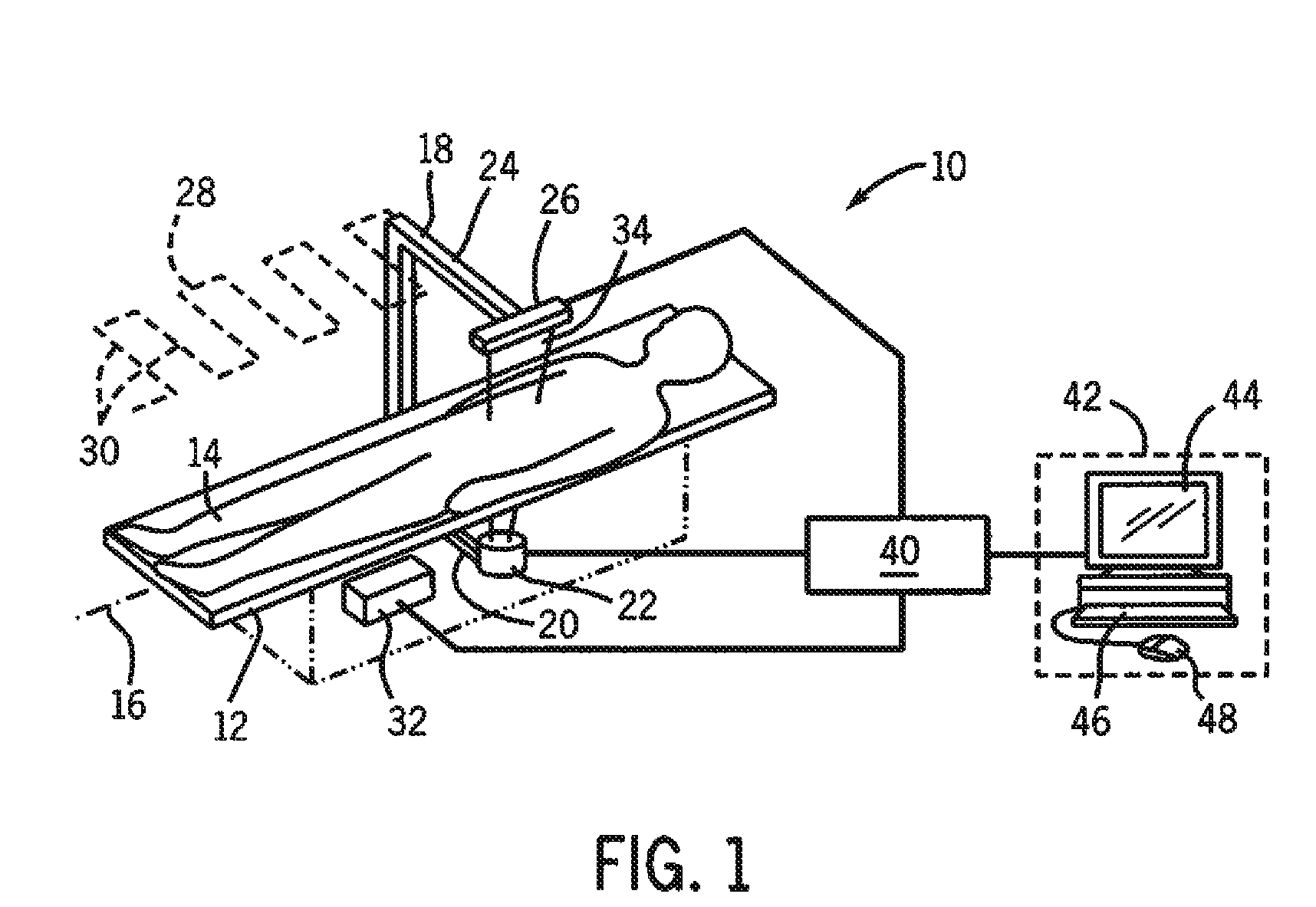
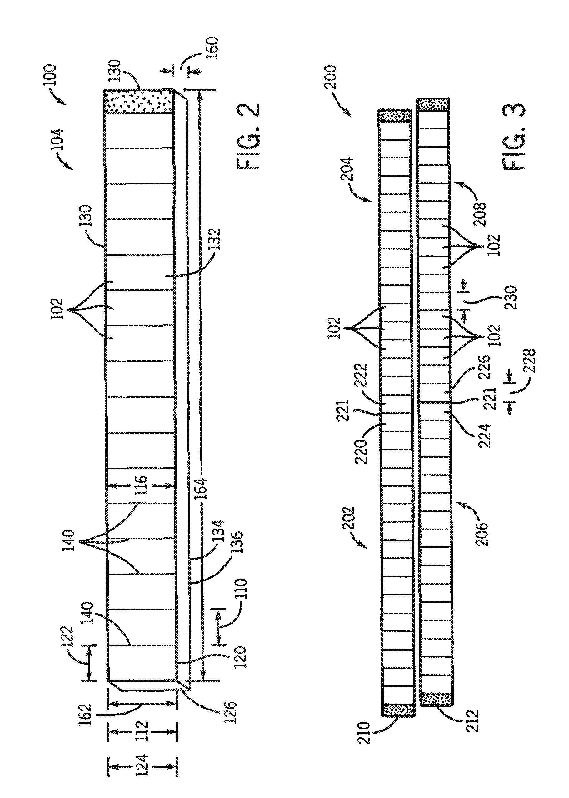
Transverse scanning bone densitometer and detector used in same

a densitometer and transverse scanning technology, applied in the field of medical diagnostic imaging systems, can solve the problem of reducing the overall quality of the signal used to generate the imag

Active Publication Date: 2012-04-24
GENERAL ELECTRIC CO
View PDF8 Cites 8 Cited by
  • Summary
  • Abstract
  • Description
  • Claims
  • Application Information

AI Technical Summary

Problems solved by technology

However, the conventional ohmic contacts may generate substantial leakage current that causes noise and thus reduces the overall quality of the signal used to generate the images.

Method used


Image

  • Transverse scanning bone densitometer and detector used in same
  • Transverse scanning bone densitometer and detector used in same
  • Transverse scanning bone densitometer and detector used in same

Examples


Embodiment Construction

[0016]The foregoing summary, as well as the following detailed description of certain embodiments, will be better understood when read in conjunction with the appended drawings. To the extent that the figures illustrate diagrams of the functional blocks of various embodiments, the functional blocks are not necessarily indicative of the division between hardware circuitry. One or more of the functional blocks (e.g., processors or memories) may be implemented in a single piece of hardware (e.g., a general purpose signal processor or random access memory, hard disk, or the like) or multiple pieces of hardware. Similarly, the programs may be stand alone programs, may be incorporated as subroutines in an operating system, may be functions in an installed software package, and the like. It should be understood that the various embodiments are not limited to the arrangements and instrumentality shown in the drawings.

[0017]As used herein, an element or step recited in the singular and proce...


PUM

PropertyMeasurementUnit
lengthaaaaaaaaaa
lengthaaaaaaaaaa
lengthaaaaaaaaaa

Abstract

A scanning bone densitometer includes an x-ray source to produce x-rays and an x-ray detector receiving x-rays emitted from the x-ray source. The x-ray detector includes a cadmium tellurium (CdTe) semiconductor. The scanning bone densitometer also includes a controller moving the x-ray source and the x-ray detector along a transverse scanning path to acquire a plurality of scan images of an object of interest.

Description

BACKGROUND OF THE INVENTION[0001]The subject matter disclosed herein relates generally to medical diagnostic imaging systems, and more particularly to bone densitometers.[0002]Dual-energy imaging systems include an x-ray source that emits a collimated beam of dual-energy x-rays to image a patient. An x-ray detector is positioned with respect to the x-ray source to receive the x-rays passing through the patient. The x-ray detector produces electrical signals in response to the received x-rays. The electrical signals are converted to digital signals that are utilized by the imaging system to generate images of the patient.[0003]Measurements of the x-ray absorption by an object at two different x-ray energies can reveal information about the composition of that object as decomposed into two selected basis materials. In the medical area, the selected basis materials are frequently bone and soft tissue. The ability to distinguish bone from surrounding soft tissue allows x-ray images to y...

Claims


Application Information

Patent Timeline
Patent Type & Authority Patents(United States)
IPC IPC(8): G01N23/06
CPCA61B6/4042A61B6/5241A61B6/482A61B6/505A61B6/4441A61B6/4241
Inventor WEAR, JAMESERGUN, DAVIDWASHENKO, ROBERTBUCHOLZ, MICHAELGORSUCH, DARRELLPAYNE, RANDALL
Owner GENERAL ELECTRIC CO
Why Eureka
Try Eureka