
Method and apparatus for wrapping a stack with a wrapping sheet

a technology of wrapping sheets and stacks, applied in the direction of wrapping/bundling articles, packaging goods, special packaging, etc., can solve the problems of uneven placement of wrapping sheets, inaccurate air nozzles, and very slow process

Inactive Publication Date: 2012-04-17
SCHUR PACKAGING SYST
View PDF22 Cites 0 Cited by
  • Summary
  • Abstract
  • Description
  • Claims
  • Application Information

AI Technical Summary

Benefits of technology

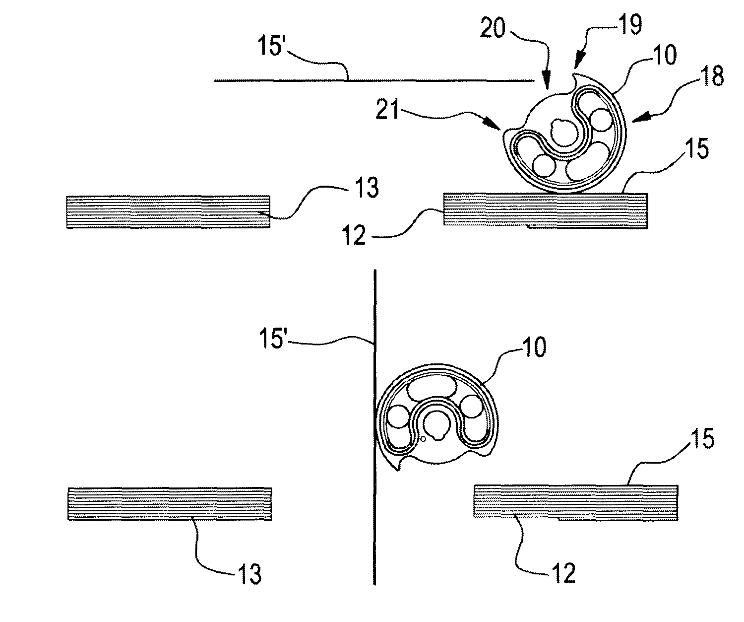
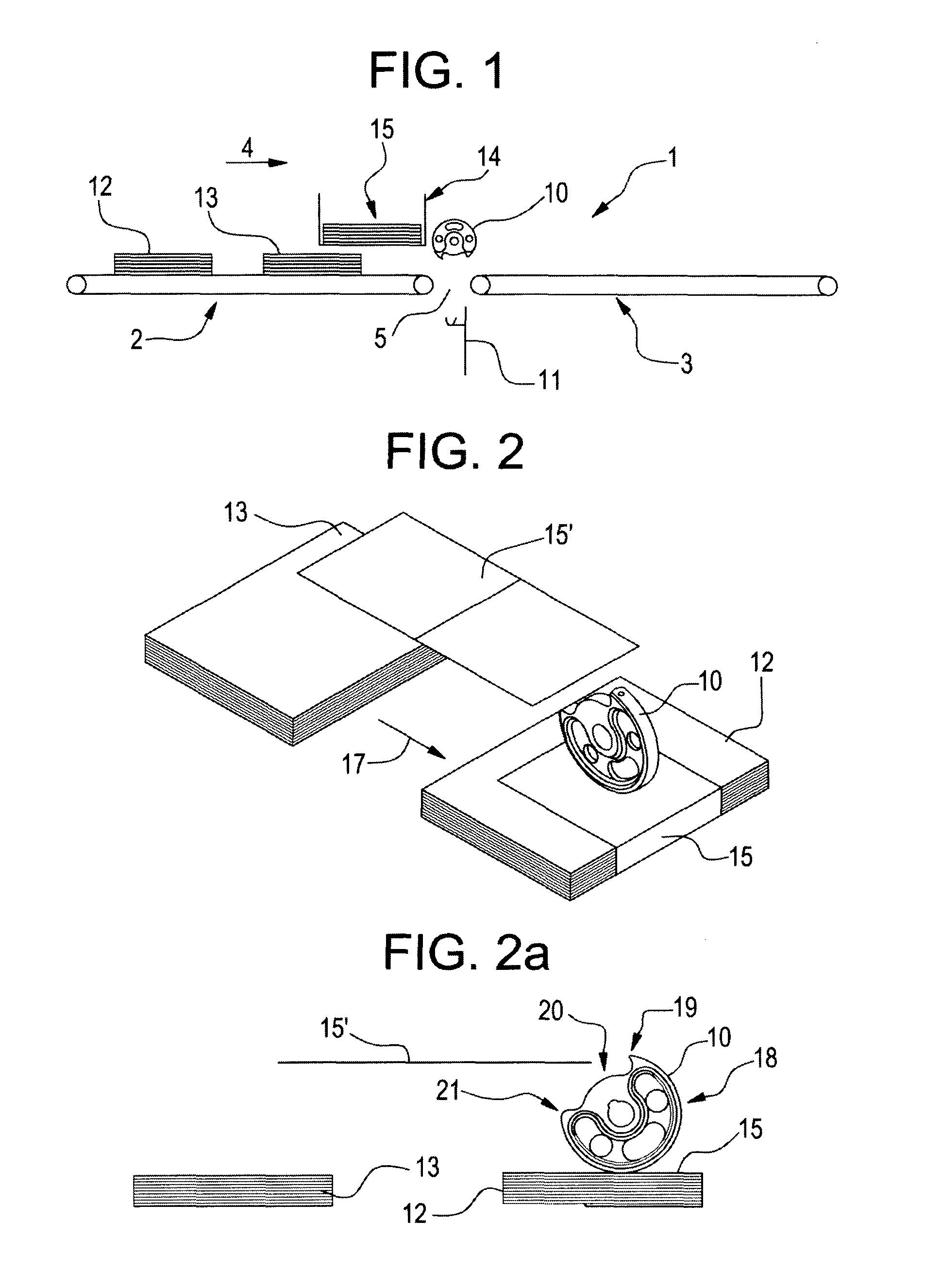
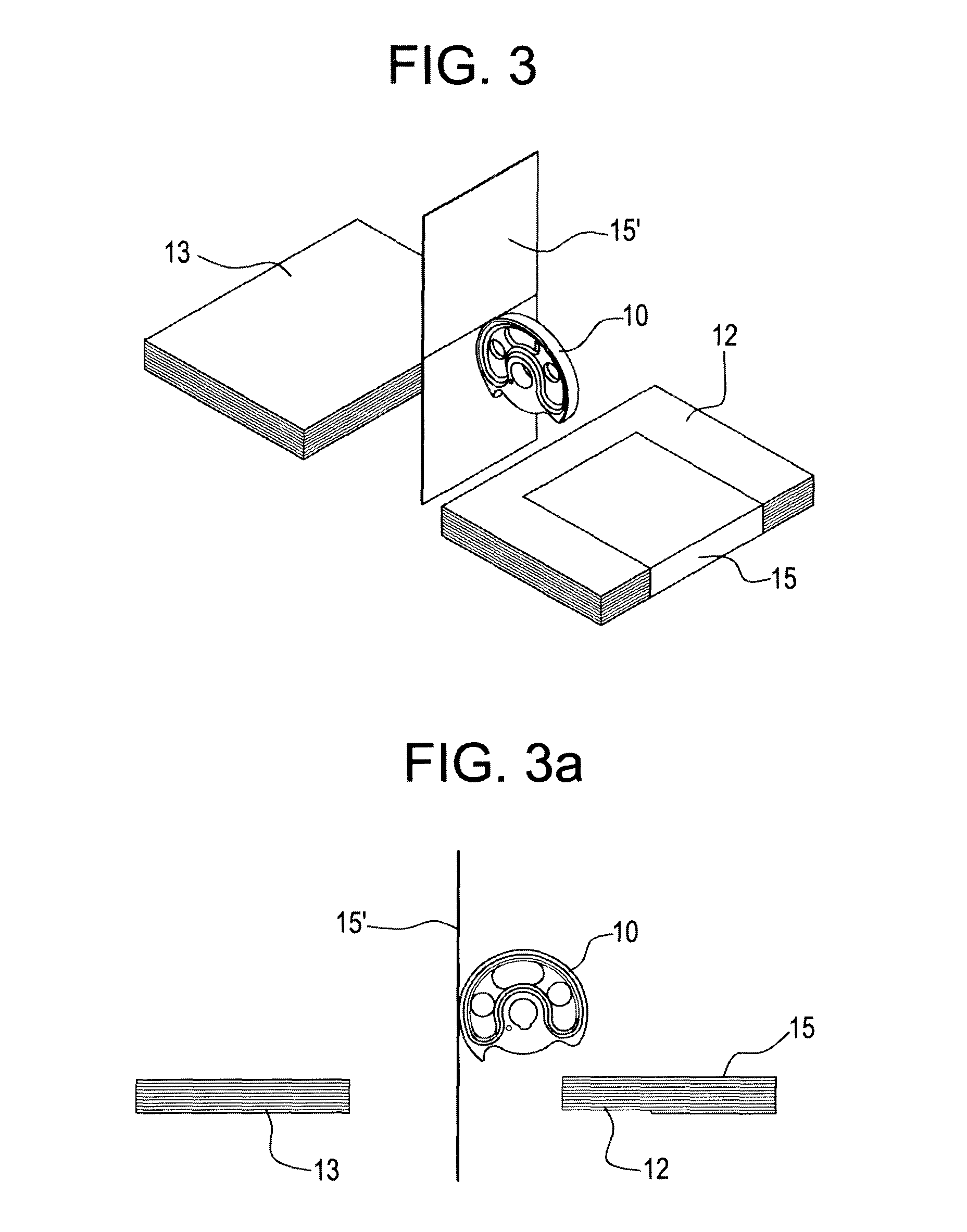
[0019]With this method and apparatus it is provided that the stack of brochures and / or folders, hereinafter referred to as the stack, is transported in a direction perpendicular to the plane of the wrapping sheet. By furthermore arranging the wrapping sheet in the proper position in relation to the stack's travelling path, for example such that the stack will engage the wrapping sheet approximately in the middle of the wrapping sheet and enhanced control of the position of the wrapping sheet in relation to the stack is ensured. This in turn provides the possibility to preform the wrapping sheet, for example by providing folding lines in the wrapping sheet or otherwise provide special features in the wrapping sheet which will require that the wrapping sheet is very accurately arranged on the stack. The use of a rotating waver wheel provides easy adjustment and timing compared to a linear translating pneumatic cylinder. Because the direction of movement is continuous and not constantly changing, there is no time of inactivity with respect to the dispensing cycle. Therefore the invention may be used in high rate production.
[0020]In a further advantageous embodiment of the invention a wrapping sheet stop or land is provided such that the inserted wrapping sheet will be held in the correct elevation in relation to the conveying path. Although the waver wheel may accurately position the sheet in the proper position relative to the stacks transport path, the wrapping sheet stop or land, makes it possible for the waver wheel to release contact from the sheet and prepare for placing the following wrapping sheet in the gap. The stop or land therefore makes it possible to either use a larger waver wheel, which in turn provides special advantages in relation to being able to provide grip or attachment means for the wrapping sheets, and / or rotate the waver wheel faster, such that an increase in productivity may be gained.
[0023]The wrapping sheet dispenser will be arranged so that the mechanism arranging the wrapping sheet in the stack's path will be able to move and carry out the different functions in the gap provided between the first and second conveyors arranged in line. The waver wheel will engage the stack of wrapping sheets and guide the wrapping sheet down into its proper position perpendicularly to the conveying path provided by the first and second conveyors arranged in line. As the stack advances it will engage the wrapping sheet brought into position by the rotating waver wheel, but in order to assure that the wrapping sheet is in its correct position relative to the stack a wrapping sheet land as foreseen in a further advantageous embodiment is provided so that as the waver wheel pulls a wrapping sheet from the dispenser and arranges this wrapping sheet perpendicularly to the travelling direction of the stack, the wrapping sheet will be placed correctly in the gap by having the waver wheel move the wrapping sheet into contact with the wrapping sheet land, which will thereafter determine the correct positioning of the wrapping sheet in relation to the conveying part. This in turn means that by adjusting the distance between the conveying path and the wrapping sheet land it is possible to adjust the positioning of the wrapping sheet in relation to the stack to be wrapped.
[0025]This embodiment is particularly useful for high-speed applications where it is desirable to accelerate the stack of superposed sheets as rapidly as possible along the conveying path. By engaging the stack both from below and from above a certain pressure will be introduced into the stack so that even at relatively high speeds no disc configuration of the stack will occur due to accelerations or other impacts. The secondary conveyors in this manner serve to maintain the integrity of the stack during the conveying. Furthermore, the second conveyor arranged downstream from the gap will fold the wrapping sheet in the same manner as the first conveyor downstream of the gap along the top side and lower side of the stack respectively and thereby complete the positioning of the wrapping sheet around or at least in contact with the stack. With this embodiment where height adjustable secondary conveyors are provided, the ability of the waver wheel to separate a single wrapping sheet from the wrapping sheet dispenser and place it in contact with the wrapping sheet land in a orientation perpendicular to the transport direction of the stack is the determining factor in how quickly the wrapping procedure may be completed.
[0026]In order to further improve this, the invention in a further advantageous embodiment provides that the waver wheel is provided with at least one suction nozzle. As the waver wheel constantly rotates preferably at a constant speed, activation of a suction nozzle will increase the probability of attaching a wrapping sheet to the waver wheel and thereby arranging it perpendicularly to the stack's transport direction. The suction nozzles may be connected to a source of vacuum which may incorporate a very quick-acting valve so that the suction may be applied and terminated very rapidly in order for waver wheel to attach itself to a wrapping sheet, pull it from the dispenser and into the gap and cut-off section in order to let the wrapping sheet lose and engage the wrapping sheet land for correct positioning in the gap in a relatively short time corresponding to the time it takes a stack to travel past the wrapping station.

Problems solved by technology

However, this process is very slow and very costly.
One drawback, however, with the prior art device and method is the fact that the stack needs to be placed on the first conveyor on top of the wrapping sheet.
If the stack is not placed correctly on top of the wrapping sheet, the wrapping induced by the air nozzles may not be correct so that the wrapping sheet is placed in an uneven manner around the stack of sheets, brochures and / or folders.
This in turn leads to unevenness when the wrapped stacks are being conveyed on to e.g. a stacker or for manual handling Furthermore, the precise positioning of the stack on top of the wrapping sheet requires that the dispensers or machines further upstream from the wrapping station work in a very precise manner in order to position the stack of sheets, brochures and / or folders correctly on the wrapping sheet.
Another drawback is the fact that when it comes to high speed conveying the stack placed on the wrapping sheet may have such a low coefficient of friction between the wrapping sheet and the stack that the acceleration on the conveyors may displace the stack in relation to the wrapping sheet so that an uneven wrapping is the result.
The method and devise provided for dispensing and positioning the wrapping material is complex and very sensitive to the correct timing of the feed rate and the operation of the pneumatic cylinders.
This causes the devise to have a longer set up time.
The reliability will be low due to the complexity and parts count, and therefore down time due to maintenance is expected to be high.
Furthermore, the productivity of the wrapper is limited, because the pneumatic cylinders are inactive during part of the cycle with respect to wrapping the bundles.
These separate sets of rollers are a complex device and as mentioned in the above cited prior art this may lead to low reliability.

Method used


Image

  • Method and apparatus for wrapping a stack with a wrapping sheet
  • Method and apparatus for wrapping a stack with a wrapping sheet
  • Method and apparatus for wrapping a stack with a wrapping sheet

Examples


Embodiment Construction

[0011]The invention addresses this by providing a method for wrapping a stack with a wrapping sheet where the stack comprises one or more substantially superposed sheets, brochures and / or folders characterised in that:[0012]a) the stack is travelling in a first direction on a first conveyor defining a conveying path and;[0013]b) that a supply of wrapping sheets are placed in line with the first conveyor either above or below the conveyor, wherein;[0014]c) a wrapping sheet supply mechanism is arranged at the downstream end of the first conveyor, which mechanism comprise a rotating waver wheel, that pulls a top sheet of the supply of wrapping sheets, turns the wrapping sheet such that the plane of the sheet is perpendicular to the travelling direction of the stack;[0015]d) a second conveyor is provided downstream of the first conveyor, such that a gap between the first and second conveyors may accommodate at least a part of the sheet supply mechanism and / or the wrapping sheet;[0016]e)...


PUM

PropertyMeasurementUnit
heightaaaaaaaaaa
suctionaaaaaaaaaa
coefficient of frictionaaaaaaaaaa

Abstract

A method and an apparatus for wrapping a stack (12, 13) of superposed sheets, brochures and / or folders with a wrapping sheet (15). The stack (13) is travelling in a first direction (4) on a first conveyor (2) defining a conveying path. A supply of wrapping sheets (14) is placed in line with the first conveyor (2). At the downstream end of the first conveyor (2) a rotating waver wheel (10) is arranged. This waver wheel pulls a top sheet (15) from the supply of wrapping sheets (14) and turns the wrapping sheet (15). Downstream of the first conveyor (2) a second conveyor (3) is provided defining a gap (5) between the first and second conveyors in which the wrapping sheet is inserted. As the stack (13) engages the wrapping sheet (15), the rotating waver wheel (10) folds the sheet around the stack.

Description

[0001]This application claims the benefit of Danish Application No. PA 200601682 filed Dec. 20, 2006 and PCT / DK2007 / 000557 filed Dec. 20, 2007, which are hereby incorporated by reference in their entirety.FIELD OF THE INVENTION[0002]The present invention relates to a method and an apparatus for wrapping a stack with a wrapping sheet where the stack comprises one or more substantially superposed sheets, brochures and / or folders.BACKGROUND OF THE INVENTION[0003]For wrapping sheets, brochures and / or folders or bundles of such matter a folded film or sheet, hereinafter called wrapping sheet, is placed around the stack. The purpose of this is to create separate stacks comprising a number of different sheets, brochures and folders, e.g. advertisements which are used for domestic distribution where the wrapping sheet separates the brochures or advertising material which need to be distributed to each household. The task of wrapping the wrapping sheet around the stack may be regarded as rel...

Claims


Application Information

Patent Timeline
Patent Type & Authority Patents(United States)
IPC IPC(8): B65B27/08B65B11/08
CPCB65B11/10B65B25/14B65B11/08
Inventor JORGENSEN, KRISTIAN
Owner SCHUR PACKAGING SYST
Learn More