
Method and system for sharing data between radiology information systems

a radiology information system and data technology, applied in the field of radiology information system sharing methods and systems, can solve the problems of increasing the number of radiology information systems that have to be set up, not always talking easily with each other, and requiring a lot of effort, so as to achieve the effect of avoiding a lot of time-consuming user involvemen

Inactive Publication Date: 2012-04-10
CSAM SWEDEN AB
View PDF20 Cites 2 Cited by
  • Summary
  • Abstract
  • Description
  • Claims
  • Application Information

AI Technical Summary

Benefits of technology

Enables seamless communication and data sharing across different radiology information systems, enhancing resource utilization and facilitating efficient workload distribution without extensive user involvement, while ensuring consistent meta-data presentation.

Problems solved by technology

Since, there are different radiology information systems on the market they will not always talk easily with each other.
However, the problem grows with the number of radiology information systems that have to be set up.
Thus, it is easy to see that this will require a lot of effort as the number of radiology information systems increase.
The drawback is that the overall resources are not used efficiently.
For example, if the workload at one hospital is high it has to deal with the problem itself, even if there are resources available at another hospital.
Another drawback is that the only way that you easily can get a second opinion is from someone working within your own system.
Sharing of experience between different hospitals is of course also difficult.
The problem when it comes to showing images on radiology information systems is not so much the showing of the image itself but the meta-data that is incorporated in the image.
This can cause a problem for the radiologist when interpreting the image together with the meta-data.

Method used


Image

  • Method and system for sharing data between radiology information systems
  • Method and system for sharing data between radiology information systems
  • Method and system for sharing data between radiology information systems

Examples


Embodiment Construction

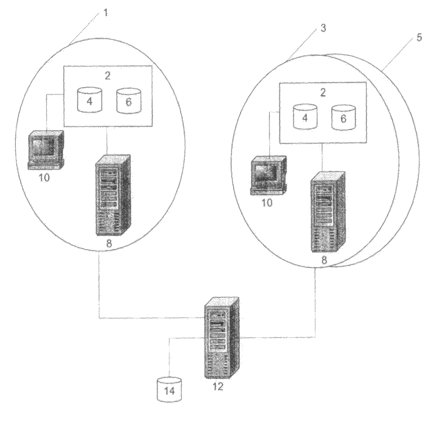
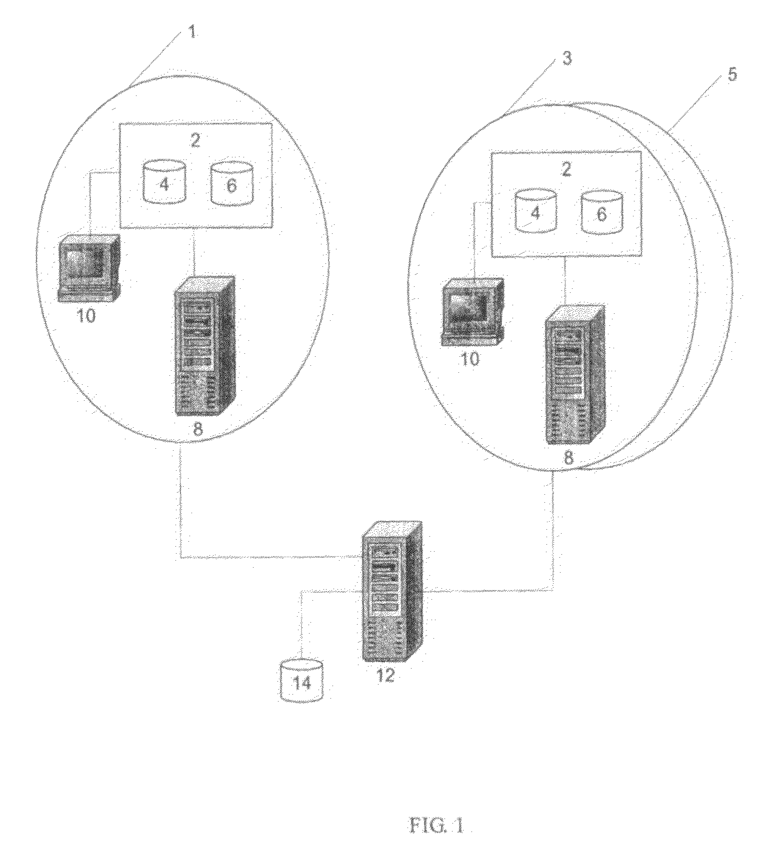
[0016]FIG. 1 shows a schematic view of the virtual radiology information system according to the invention. The radiology system at one hospital or department 1 comprises a RIS-PACS system 2, having the RIS database 4 and the PACS database 6. To access the information in the RIS-PACS system 2 an ordinary workstation 10 is connected thereto. Furthermore, the RIS-PACS system 2 is connected to a send and receive server 8, which enables the RIS-PACS system 2 to communicate with the outside world. The outside world in this case is other hospitals or departments 3 and 5. The radiology departments 3 and 5 are set up in a similar way as the radiology department 1. A central server 12 interconnects the different hospitals or departments 1, 3 and 5. A central storage unit 14 is connected to central the server 12.

[0017]The above mentioned system, configured to perform the method according to the invention, constitutes a virtual radiology information system in which stored information in one RI...


PUM


Abstract

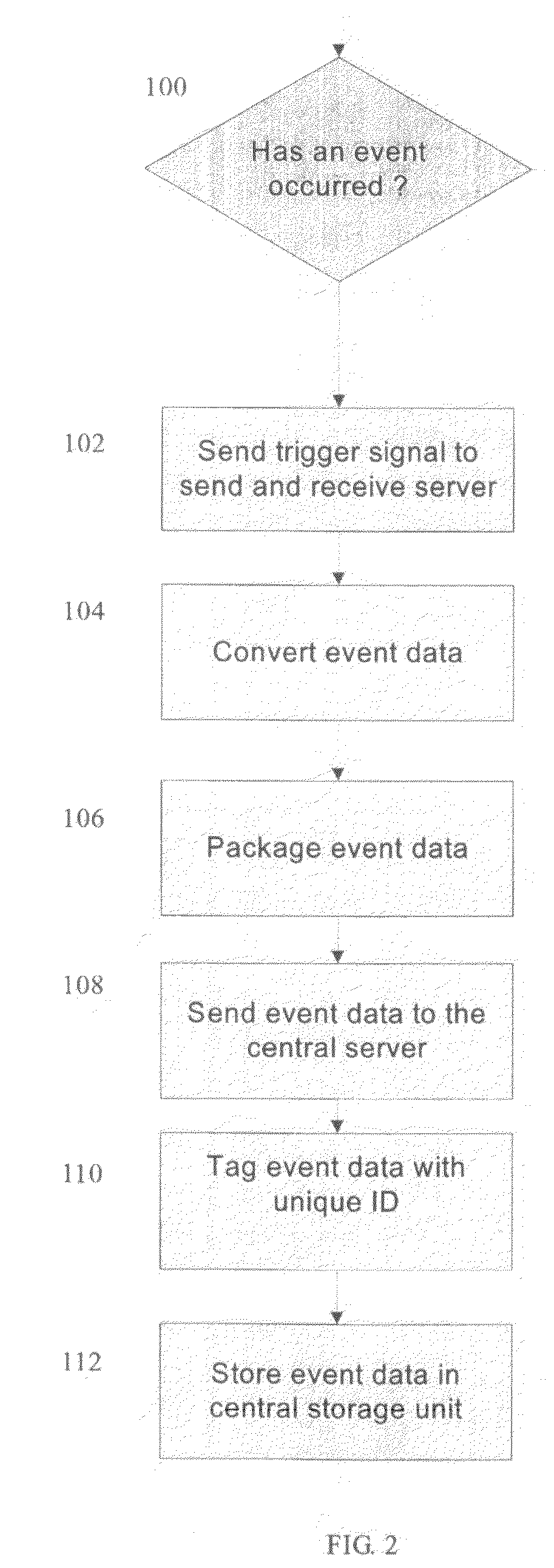
The present invention relates to a method and a system for sharing and exchanging event data between at least two 5 radiology information systems. An event in any of the radiology information systems triggers a send and receive server to convert the event data from the radiology information system that has sent out the trigger signal. The send and receive server than then packages the converted 10 data and sends the converted and packed data from the send and receive server to a central server. The central server tags the received data and stores the received data at a central storage unit connected to the central server. Finally, the central server sends the stored data back to 15 any of the radiology information systems via the send and receive server at the request by any of the radiology information systems and if the stored data comprises images exchange the exciting meta-data with meta-data generated by the send and receive server (8) of the receiving radiology 20 information system (2).

Description

TECHNICAL FIELD[0001]The present invention relates to a method and a system for sharing data between at least two radiology information systems.PRIOR ART[0002]Today there exist a lot of radiology information systems, which help and support the people working with radiology. This is sufficient as long as one hospital works with its own radiology data. However, if a group of hospitals or different sites at a hospital want to work more closely together with each other and coordinate their work and learn from each other's experience they have to start sharing data with each other. Since, there are different radiology information systems on the market they will not always talk easily with each other. If two different radiology information systems have to talk to each other it is not a major problem. Each radiology information system can be set up such as it can communicate with the other. However, the problem grows with the number of radiology information systems that have to be set up. ...

Claims


Application Information

Patent Timeline
Patent Type & Authority Patents(United States)
IPC IPC(8): G06F15/16G06Q50/00G06Q10/00G16H10/60G16H15/00G16H30/20G16H30/40G16H40/67
CPCG06F19/321G06Q50/24G06Q10/06G06Q50/22G06F19/3425G06F19/3487G16H80/00G16H15/00G16H30/20G16H30/40G16H40/67
Inventor WALLBERG, JOACHIM
Owner CSAM SWEDEN AB
Learn More