
Disc brake caliper with a cooling duct

a technology of disc brake calipers and cooling ducts, which is applied in the direction of braking discs, fluid actuated brakes, hoisting equipment, etc., can solve the problems of generating considerable heat flows towards the brake caliper, complex manufacturing and assembly of the caliper body, and ineffective brakes

Active Publication Date: 2012-04-10
FRENI BREMBO SPA
View PDF17 Cites 16 Cited by
  • Summary
  • Abstract
  • Description
  • Claims
  • Application Information

AI Technical Summary

Benefits of technology

The present invention provides a disc brake caliper that overcomes the drawbacks and restrictions of prior art. The caliper has improved performance and efficiency. Other embodiments of the caliper are described in the subsequent claims.

Problems solved by technology

The discs of disc brakes, mainly on high performance vehicles, are known to reach a high temperature, thereby generating considerable heat flows towards the brake caliper which tends to be overheated.
This overheating may be very dangerous for the brake liquid that may cause the brake to be completely ineffective, in the event it reaches the boiling temperature.
However, this air stream is very hot and often not only it does not ensure sufficient cooling, but can be even counter-productive.
On the other hand, even the latter solution, though being satisfactory under several aspects, is very complicated to manufacture and assemble in the caliper body, and above all it is not suitable for calipers mounted on high performance vehicles being equipped with pistons provided on both disc sides.
This solution, however, tends to weaken the caliper body, which is subjected when breaking to high flexural stress being maximum just at the central bridge.
Furthermore, this channel is often overheated by the heat from the brake disc.

Method used


Image

  • Disc brake caliper with a cooling duct
  • Disc brake caliper with a cooling duct
  • Disc brake caliper with a cooling duct

Examples


Embodiment Construction

[0036]The elements or parts of elements in common between the embodiments described below will be designated with the same numerals.

[0037]By “radial direction” is meant a direction substantially perpendicular to the X rotation axis of the disc brake associable to the disc brake caliper.

[0038]By “axial direction” is meant a direction substantially parallel to the X rotation axis of the brake disc.

[0039]By “tangential direction” is meant a direction substantially perpendicular to the axial direction and the radial direction, as well as parallel to the braking band of the associable brake caliper.

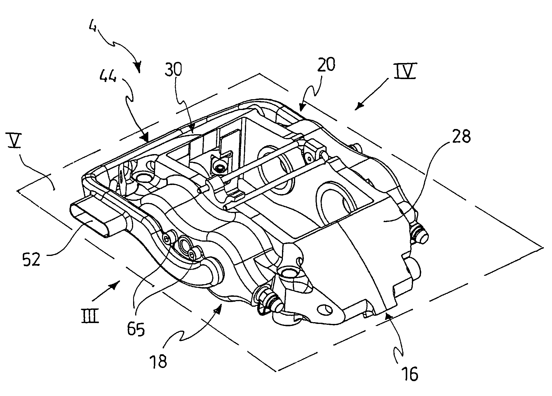
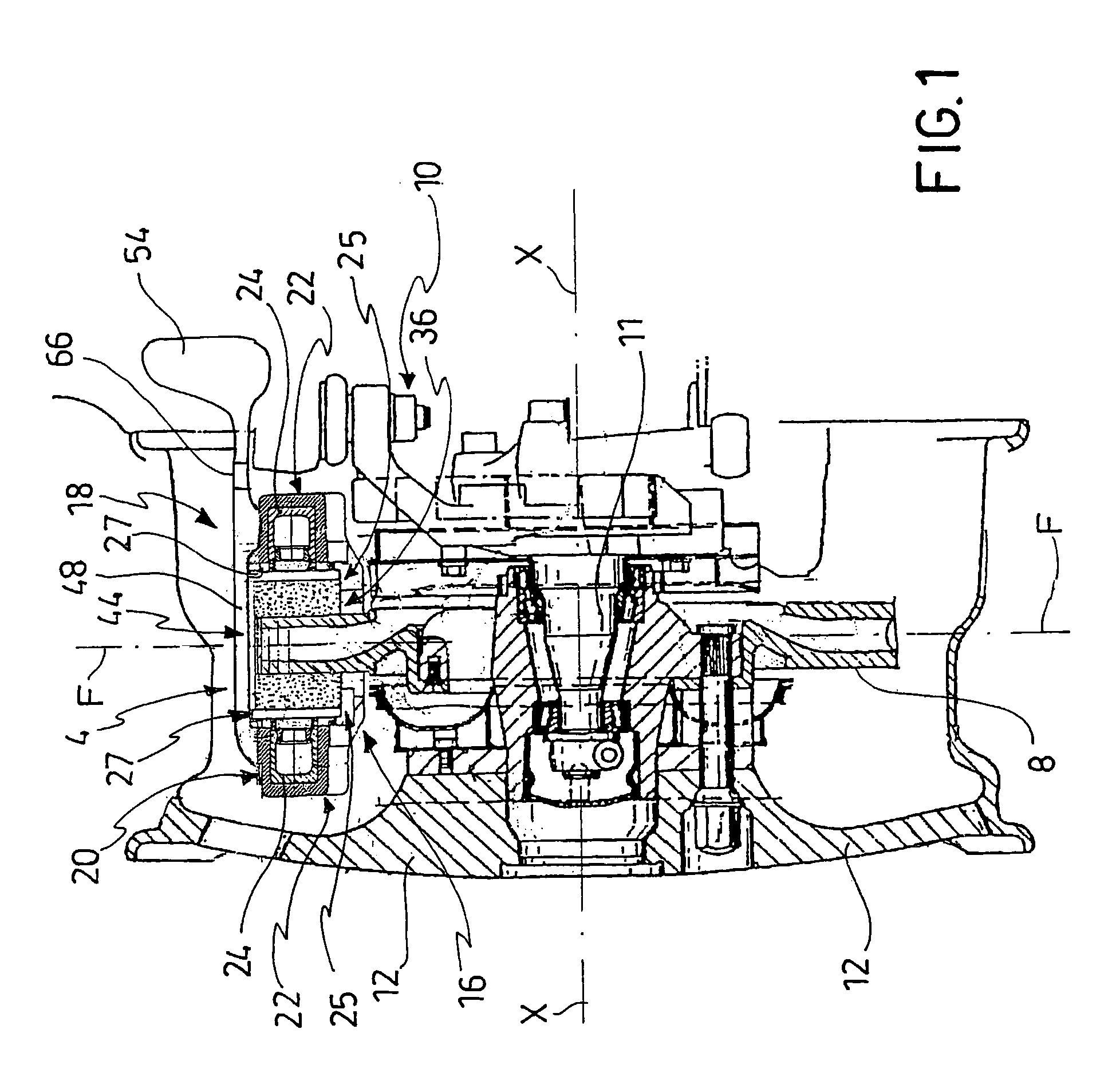
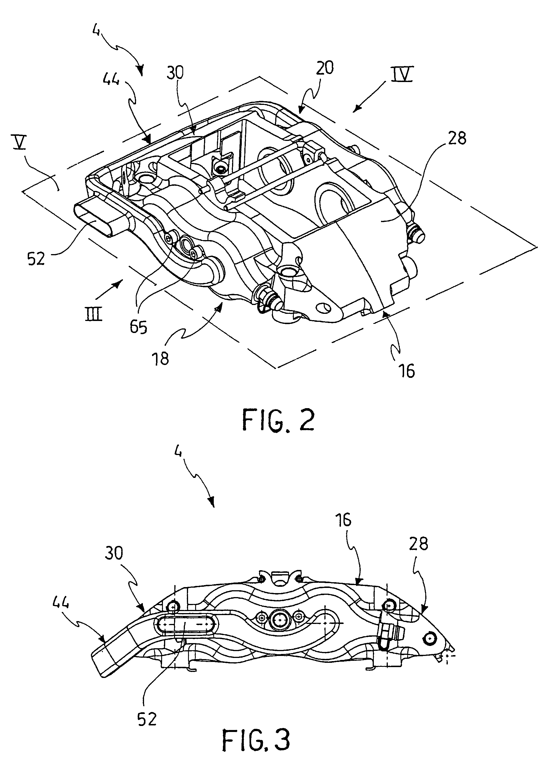
[0040]With reference to said figures, with 4 there has been generally indicated a disc brake caliper, suitable to be mounted astride a brake disc 8 pivoting about its rotation axis X.

[0041]Said caliper 4 is suitable to be supported by a suspension 10 comprising a hub 11, a wheel 12 being associable thereto, such that the caliper is comprised between the suspension 10 and the wheel 12, such as ...


PUM


Abstract

A disc brake caliper comprising a suspension side portion, facing an associable suspension to support said caliper, a wheel side portion facing a wheel being rotatably integrally associable to a brake disc, said wheel side and suspension side portion comprising cylinders suitable to house pistons facing pads for breaking the brake disc, and being connected by at least one connecting bridge extending astride the brake disc. The caliper comprises at least one casing being associable to a side surface of said caliper opposite a housing recess of the brake disc, such as to define a duct extending between said suspension side and wheel side portion to convey a cooling air steam, near thrust portion of the pads being affected by the relative pistons.

Description

FIELD OF THE INVENTION[0001]The present invention relates to a disc brake caliper, and particularly, a disc brake caliper suitable to be mounted to high performance vehicles.BACKGROUND OF THE INVENTION[0002]The discs of disc brakes, mainly on high performance vehicles, are known to reach a high temperature, thereby generating considerable heat flows towards the brake caliper which tends to be overheated. This overheating may be very dangerous for the brake liquid that may cause the brake to be completely ineffective, in the event it reaches the boiling temperature.[0003]In order to overcome these drawbacks, different solutions are known from the prior art.[0004]For example, DE 3833552 provides pads, wherein the pad plate suitable to be compressed by the caliper piston head comprises radial cavities on the side directly facing said cylinders. The piston head also comprises cavities allowing an air stream to pass through the interface area between the pistons and the pads. This air st...

Claims


Application Information

Patent Timeline
Patent Type & Authority Patents(United States)
IPC IPC(8): F16D65/847
CPCF16D55/228F16D65/847F16D2055/0016
Inventor CORNOLTI, RAFFAELLOARRIGONI, RICCARDOPERSICO, SILVIO
Owner FRENI BREMBO SPA
Learn More