
Wheel and hub assembly

a technology of hubs and wheels, applied in the direction of hubs, transportation and packaging, refuse gathering, etc., can solve the problems of inability to replace or repair wheels or carts, damage to axles, unduly complex snap-on wheel assemblies, etc., and achieve the effect of slowing assembly and increasing costs

Active Publication Date: 2012-04-03
GEO PLASTICS
View PDF31 Cites 30 Cited by
  • Summary
  • Abstract
  • Description
  • Claims
  • Application Information

AI Technical Summary

Benefits of technology

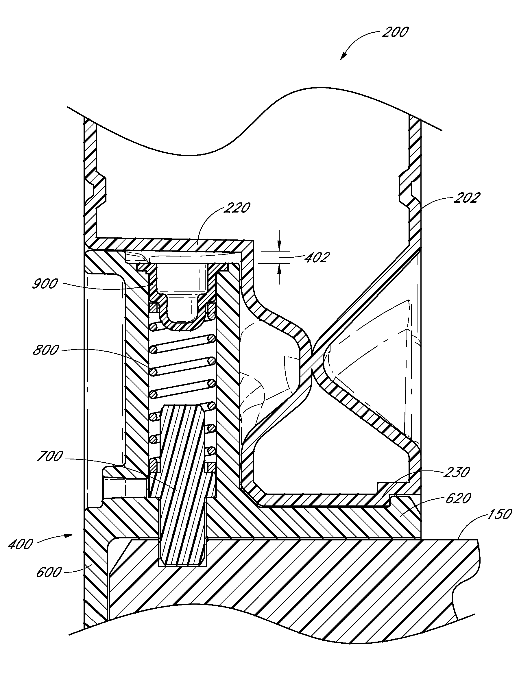
[0005]The design of certain prior wheel and hub assemblies limits the extent of automatic assembly of a wheel and hub assembly because the pin and spring would be expelled from the wheel assembly without a portion of the wheel to keep them in place. The hub assembly may be specifically oriented such that the pin and spring do not fall out until coupling to a wheel. However, manipulation of the hub assembly such as transporting, dropping, turning, and especially vibration caused by automating equipment can cause the pin and spring to become lost before assembly, increasing costs and slowing assembly due to insertion of replacement parts. Additionally, foreign debris can enter the open end of a pin sleeve all the way until assembly with a wheel. Thus, the pin and spring are generally installed during coupling of the wheel and a hub assembly. Upon disengagement of the wheel from such hub assemblies, which may occur when a wheel assembly is broken (e.g., due to splitting of the wheel from shock loading), the pin and spring can be expelled from the hub assembly to be lost or damaged.
[0006]At least one aspect of the present invention is the realization of the advantages gained from a restraining element such as a plug that prevents the pin and spring from being separated from the hub assembly upon manipulation without being coupled to a wheel. Once the plug is coupled to the pin sleeve after the pin and spring are inserted therein, the hub assembly can be fully manipulated without causing separation of the components because the plug prevents the pin and spring from coming out of the pin sleeve. The hub assembly can thus be formed well before it is coupled to the wheel, allowing resources to be allocated without regard to the quantity of any component (i.e., more hub assemblies can be made even if there are no wheels to couple them to because they can be stored without the fear of losing pieces). The plug also allows fully automated assembly because the hub assembly can be oriented in any direction and can be positioned by a vibratory feeder. Moreover, if a wheel is damaged, the hub assembly, which is typically the more expensive component, can be coupled to another wheel because all of its pieces are still in tact and accounted for.

Problems solved by technology

Removal of such plastic wheels in order to replace or repair the wheel or the cart can be difficult because the hammered push-on hat fasteners or hubs require special tools for their removal, or essentially must be destroyed to remove them from the axle.
Sometimes this process also damages the axles.
However, these snap-on wheel assemblies have been unduly complex, visually unappealing, and poorly suited to the shock loading and vibration commonly encountered.
The design of certain prior wheel and hub assemblies limits the extent of automatic assembly of a wheel and hub assembly because the pin and spring would be expelled from the wheel assembly without a portion of the wheel to keep them in place.
However, manipulation of the hub assembly such as transporting, dropping, turning, and especially vibration caused by automating equipment can cause the pin and spring to become lost before assembly, increasing costs and slowing assembly due to insertion of replacement parts.
Additionally, foreign debris can enter the open end of a pin sleeve all the way until assembly with a wheel.
Upon disengagement of the wheel from such hub assemblies, which may occur when a wheel assembly is broken (e.g., due to splitting of the wheel from shock loading), the pin and spring can be expelled from the hub assembly to be lost or damaged.
Moreover, if a wheel is damaged, the hub assembly, which is typically the more expensive component, can be coupled to another wheel because all of its pieces are still in tact and accounted for.

Method used


Image

  • Wheel and hub assembly
  • Wheel and hub assembly
  • Wheel and hub assembly

Examples


Embodiment Construction

[0040]Although certain preferred embodiments and examples are disclosed below, it will be understood by those in the art that the invention extends beyond the specifically disclosed embodiments and / or uses of the invention and obvious modifications and equivalents thereof. Thus, it is intended that the scope of the invention herein disclosed should not be limited by the particular disclosed embodiments described below.

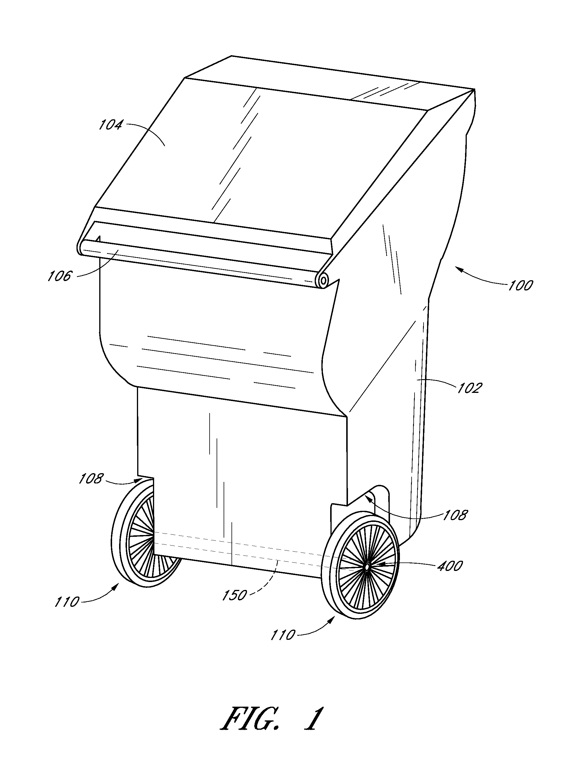
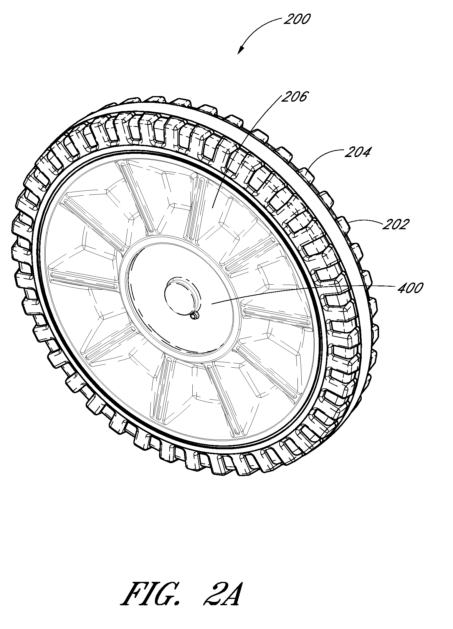
[0041]The wheel assemblies described herein can be used in connection with numerous wheeled devices. FIG. 1 illustrates an example embodiment of a refuse cart comprising plurality of wheel assemblies 110 mounted on an axle 150 to the lower end of the cart body 102. A hinged lid 104 optionally can be provided, and the cart 100 can be tilted or tipped about the wheel assemblies 200 using handle 106 so as to enable rolling of the cart 100 for the transport of refuse, for example between a location for filling the cart 100 and a location for pickup by a refuse disposal com...


PUM

PropertyMeasurementUnit
thickaaaaaaaaaa
timeaaaaaaaaaa
rotationaaaaaaaaaa

Abstract

A wheel assembly includes a wheel and a hub assembly. The hub assembly includes a retainer housing, retaining member, biasing element, and restraining element. The retainer housing includes a wheel mounting sleeve and pin sleeve. The wheel mounting sleeve includes an axle bore configured to receive an axle and configured to be inserted within a sleeve bore of the wheel. The pin sleeve includes a first end fluidly communicating with the sleeve bore, a second end, and a conduit therebetween. The retaining member, disposed within the conduit, is configured to operatively engage an axle groove and includes a lip wider than a first end shoulder to prevent the retaining member from exiting the first end. The biasing element, disposed within the conduit, is configured to bias the retaining member towards the axle bore. The restraining element is configured to prevent the retaining member from exiting the second end.

Description

BACKGROUND[0001]1. Field[0002]The present invention generally relates to wheel assemblies and the manner of their mounting to and removal from an axle, and more particularly, to wheel and hub assemblies used on refuse carts and the like.[0003]2. Description of the Related Art[0004]The use of plastic wheels on a variety of products has dramatically increased in recent years. One area where such plastic wheels have been widely employed is on wheeled refuse or garbage carts or bins of the type commonly employed by homeowners for their trash. These carts traditionally have plastic wheels that are mounted on the ends of a metal axle by a hub member or push-on hat fastener (sometimes referred to as “pawl nut”). The wheel hub is hammered onto the end of the axle to hold the wheel in place. Removal of such plastic wheels in order to replace or repair the wheel or the cart can be difficult because the hammered push-on hat fasteners or hubs require special tools for their removal, or essentia...

Claims


Application Information

Patent Timeline
Patent Type & Authority Patents(United States)
IPC IPC(8): B60B5/02
CPCB60B27/065B60B27/00B21D53/26B60B37/10B65F1/1473Y10T29/49533Y10T29/49492B60B2200/41B60B2320/10B60B2320/50B60B2320/52B60B2900/212B60B2900/3312B60B27/02B60B2360/32
Inventor MORRIS, MICHAEL A.
Owner GEO PLASTICS
Learn More