
Umbrella holder

a technology of umbrellas and holders, applied in the field of umbrella holders, can solve the problems of visual discomfort, harming users, and taking lots, and achieve the effect of safe and comfortable us

Active Publication Date: 2012-04-03
UNIQUE PRODS & DESIGN
View PDF16 Cites 38 Cited by
  • Summary
  • Abstract
  • Description
  • Claims
  • Application Information

AI Technical Summary

Benefits of technology

[0009]The first objective of this invention is to offer an umbrella holder integral in the external look and safe and comfortable in use.
[0010]The second objective of this invention is to offer an umbrella holder quick in its angle adjustment and in its disassembly and convenient in operation.

Problems solved by technology

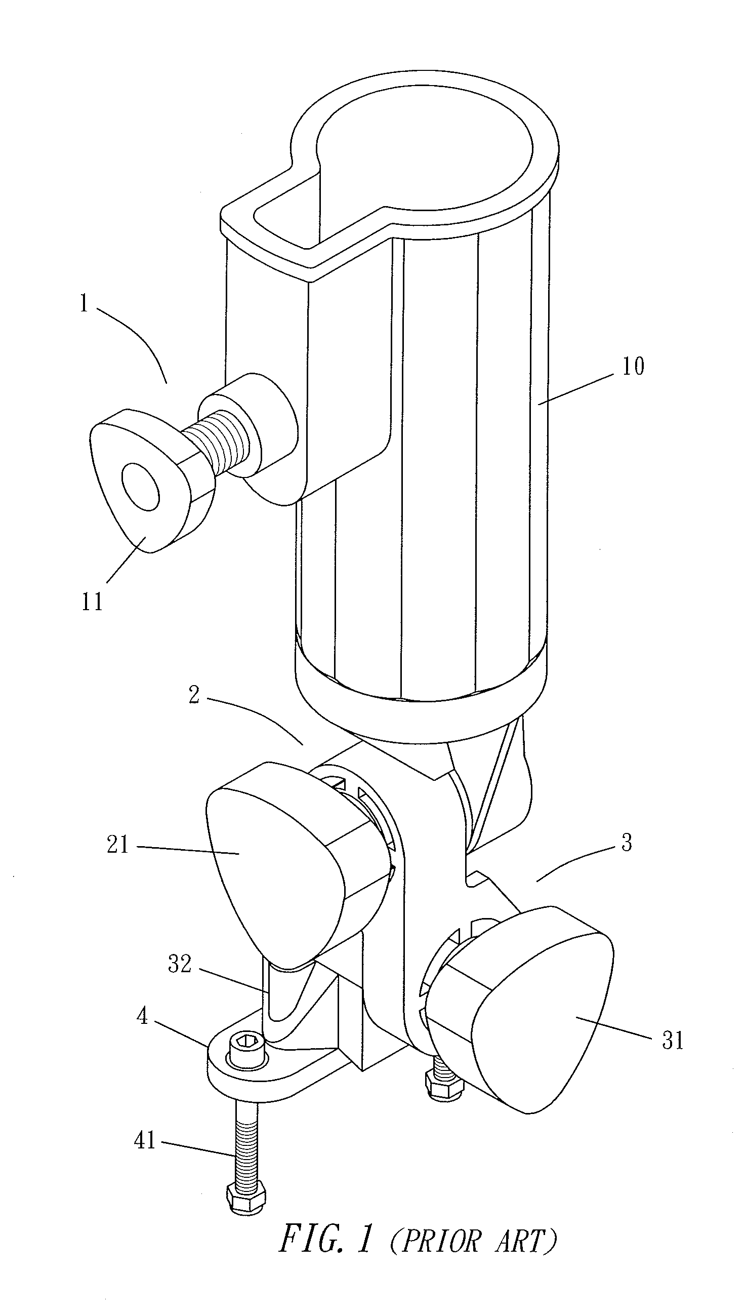
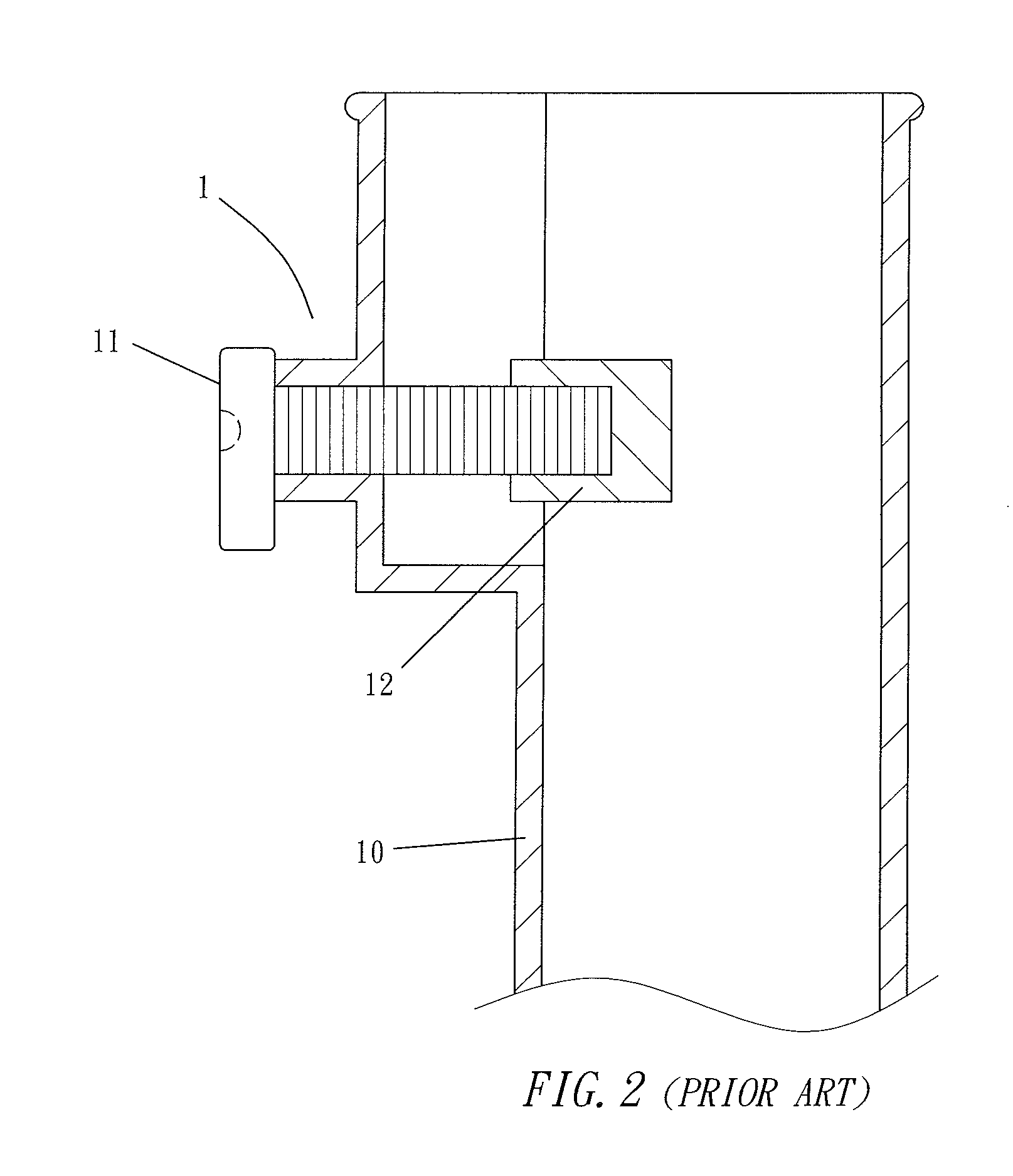
However, the conventional umbrella holder has the following drawbacks that need to be improved.1. When the fixing mechanism 1 is released, the first rotary button 11 will protrude out of the tube 10 to spoil the whole external look, not only resulting in visual discomfort, but also likely to harm a user in case of bumping against the protruding first rotary button 11.2. The second and third rotary buttons 21, 31 must be turned around for several rounds in order to adjust the angles of the tube 10, causing much trouble and taking lots of time.3. To disassemble the tube 10, the second rotary button 21 has to be turned and released for about eight rounds so that the second rotary button 21 and the two angle-adjusting devices 2, 3 can respectively be separated from the tube 10, thus causing trouble, taking much time and being liable to cause loss of parts (buttons).

Method used


Image

  • Umbrella holder
  • Umbrella holder
  • Umbrella holder

Examples


Embodiment Construction

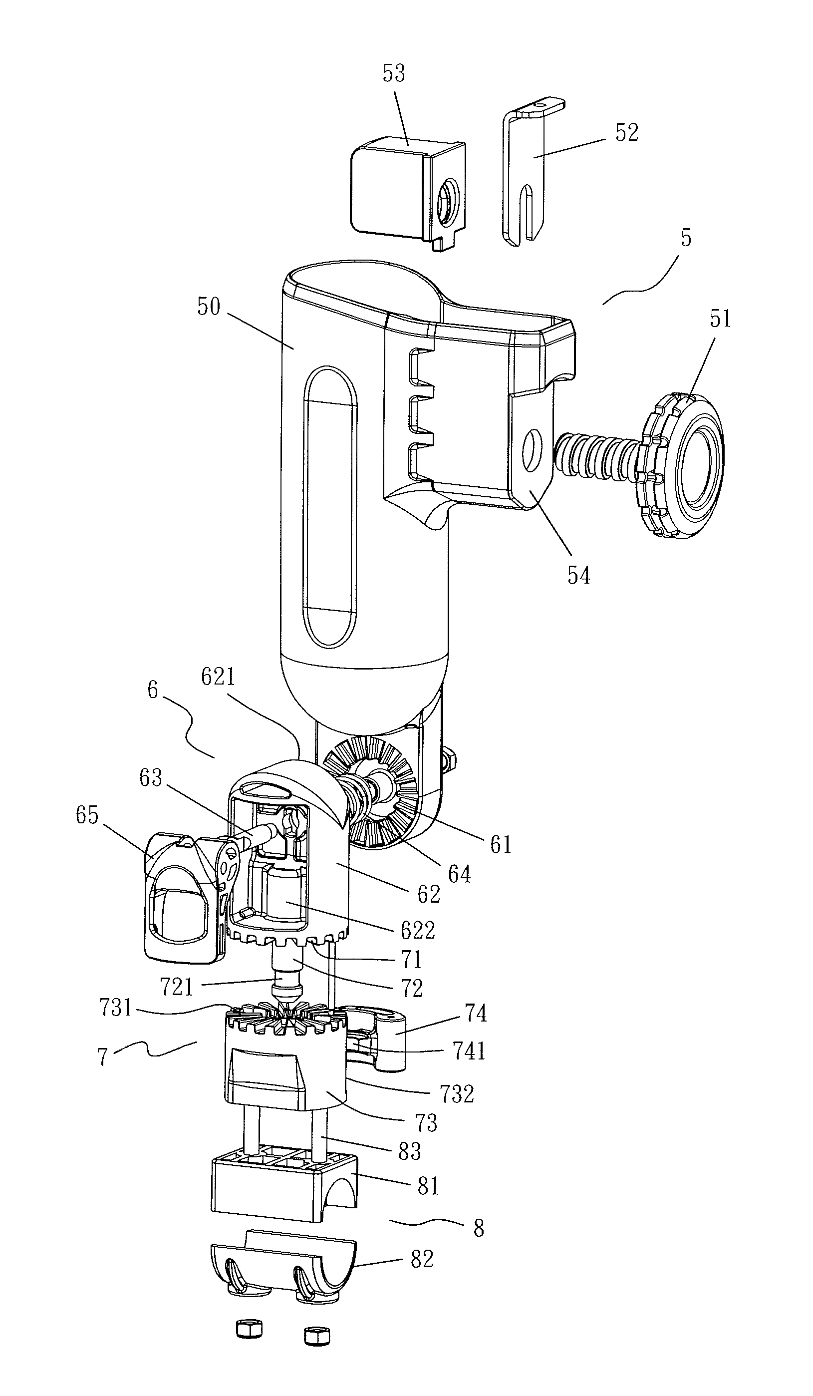
[0024]A preferred embodiment of an umbrella holder in the present invention, as shown in FIGS. 3-7, includes a fixing mechanism 5, a first adjusting mechanism 6, a second adjusting mechanism 7 and a pipe sleeve 8 as main components combined together.

[0025]The fixing mechanism 5 assembled on a hollow tube 50 is composed of a rotary button 51 with a threaded rod, a stop plate 52 and a fixing block 53. The threaded rod of the rotary button 51 is inserted in the interior of the tube 50 and has its end screwed with the fixing block 53, with the rotary button 51 flatly and closely attached in a recess 54 at an outer side of the tube 50. The stop plate 52 has its lower end mounted astride on the threaded rod of the rotary button 51 and its upper end inserted in the tube 50 for stabilizing and positioning the rotary button 51 and letting the threaded rod turn idle. When the rotary button 51 is turned around, the fixing block 53 will be actuated to shift backward and forward for releasing or...


PUM


Abstract

An umbrella holder includes a hollow tube for placing an umbrella handle. A fixing mechanism assembled is on the hollow tube and has a rotary button with a threaded rod screwed with a fixing block in the tube for tightening or releasing the umbrella handle, with a stop plate positioning the threaded rod of the rotary button. A first angle-adjusting mechanism is positioned under the hollow tube and has an immovable geared disk and a movable geared disk mounted on a rotary base and has an eccentric actuating member to engage or disengage the immovable and the movable geared disks. The holder also has a second angle-adjusting mechanism assembled under the first angle-adjusting mechanism and having an immovable geared disk with a fixed shaft and a movable geared disk disposed on a base having an eccentric actuating member for engaging or disengaging the immovable and the movable geared disks of the second angle-adjusting mechanism.

Description

BACKGROUND OF THE INVENTION[0001]1. Field of the Invention[0002]This invention relates to an umbrella holder and, particularly, to an umbrella holder which is safe and comfortable in use and convenient and quick in operation.[0003]2. Description of the Prior Art[0004]A conventional umbrella holder, as used for a golf handcart, is assembled on a handle or a scoreboard. The conventional umbrella holder, as shown in FIGS. 1 and 2, includes a fixing mechanism 1, two angle-adjusting devices 2, 3 and a fixing plate 4 combined together. The fixing mechanism 1 mounted on a hollow tube 10 is provided with a first rotary button 11 with a threaded rod for actuating a fixing block 12 to shift and tighten or release an umbrella handle placed in the interior of the hollow tube 10. The two angle-adjusting devices 2, 3 positioned under the tube 10 are respectively disposed with a second rotary button 21 and a third rotary button 31 that are rotated to turn geared disks for adjusting various angles ...

Claims


Application Information

Patent Timeline
Patent Type & Authority Patents(United States)
IPC IPC(8): F16M13/00F16M11/00A01K97/10A47F5/00E04G3/00H01Q1/12A47G29/00A47G33/12A45B25/28
CPCA45B11/00A63B55/08B60R7/12B62B3/00B62B9/147F16M11/10F16M11/2014F16M13/022A45B25/08Y10T403/32827A63B2055/082B62B5/0013F16M2200/021F16M2200/024Y10T403/32368A63B2055/602A63B55/60
Inventor LIAO, GORDON
Owner UNIQUE PRODS & DESIGN
Learn More