
Actuating element for the parking lock of a transmission and parking lock for a transmission

a technology for actuating elements and transmissions, which is applied in the direction of gearing details, braking systems, transportation and packaging, etc., can solve the problems of inability to use axial pawl actuation, high design cost, and inability to meet the requirements of axial pawl actuation, so as to reduce the structural space needed, uniform force transfer, and the effect of being particularly small

Active Publication Date: 2012-04-03
ZF FRIEDRICHSHAFEN AG
View PDF12 Cites 3 Cited by
  • Summary
  • Abstract
  • Description
  • Claims
  • Application Information

AI Technical Summary

Benefits of technology

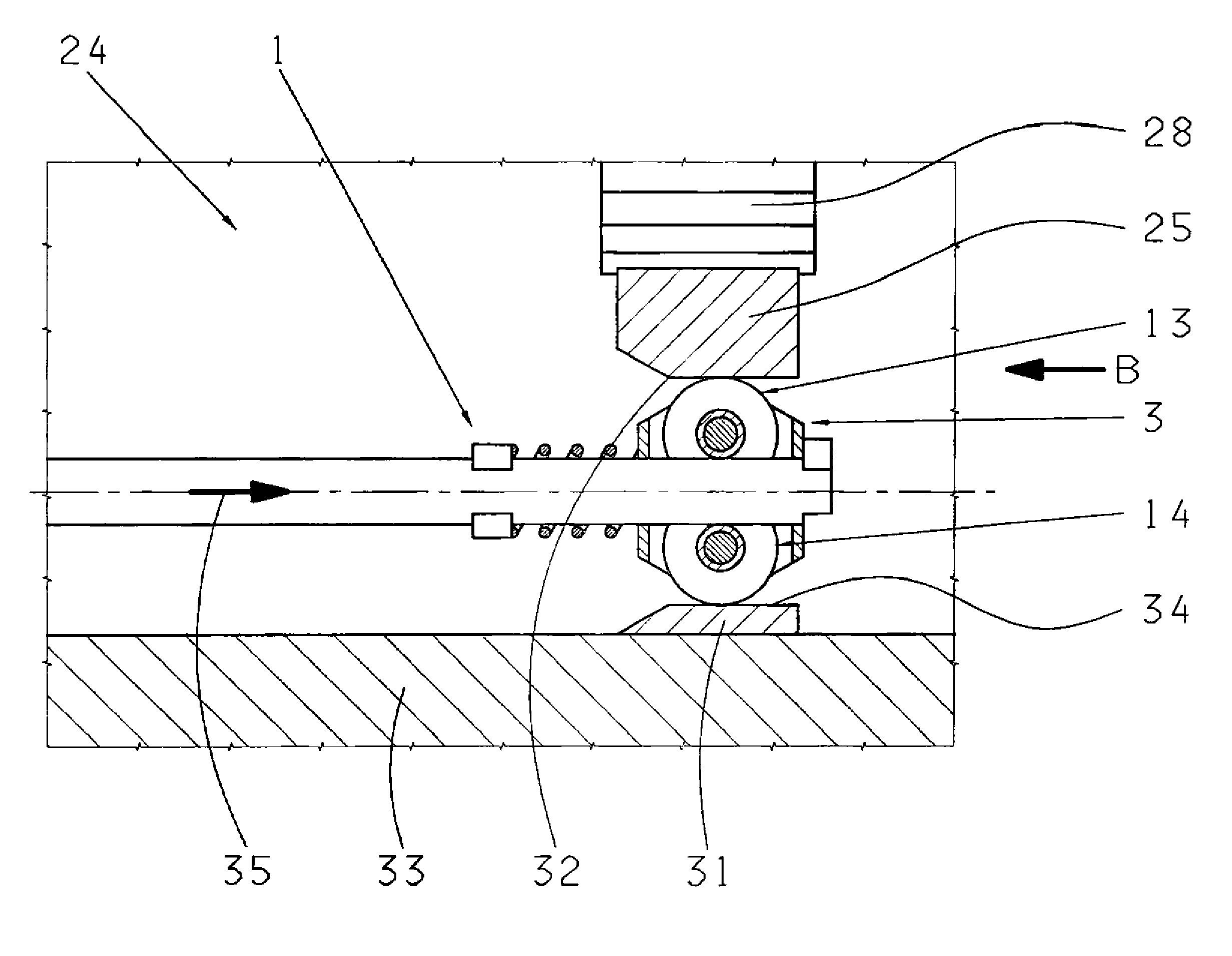
[0008]The invention has the advantage that no or no elaborate guide on the housing is needed for the roller carrier since this is guided on the positioning rod itself. This reduces the number of components and corresponding connection points so that the actuating element as a whole is less prone to malfunction and takes up less structural space. The latter characteristic, in particular, makes it possible to use the actuating element in a parking lock with axial pawl actuation. Furthermore, owing to the compact design, the positioning rod of the actuating element can even have several bends in it and does not have to be straight. This enables the positioning rod to be located almost anywhere within the parking lock so that the other parts of the device, such as the selector shaft and the retaining disk, can be positioned virtually as desired.
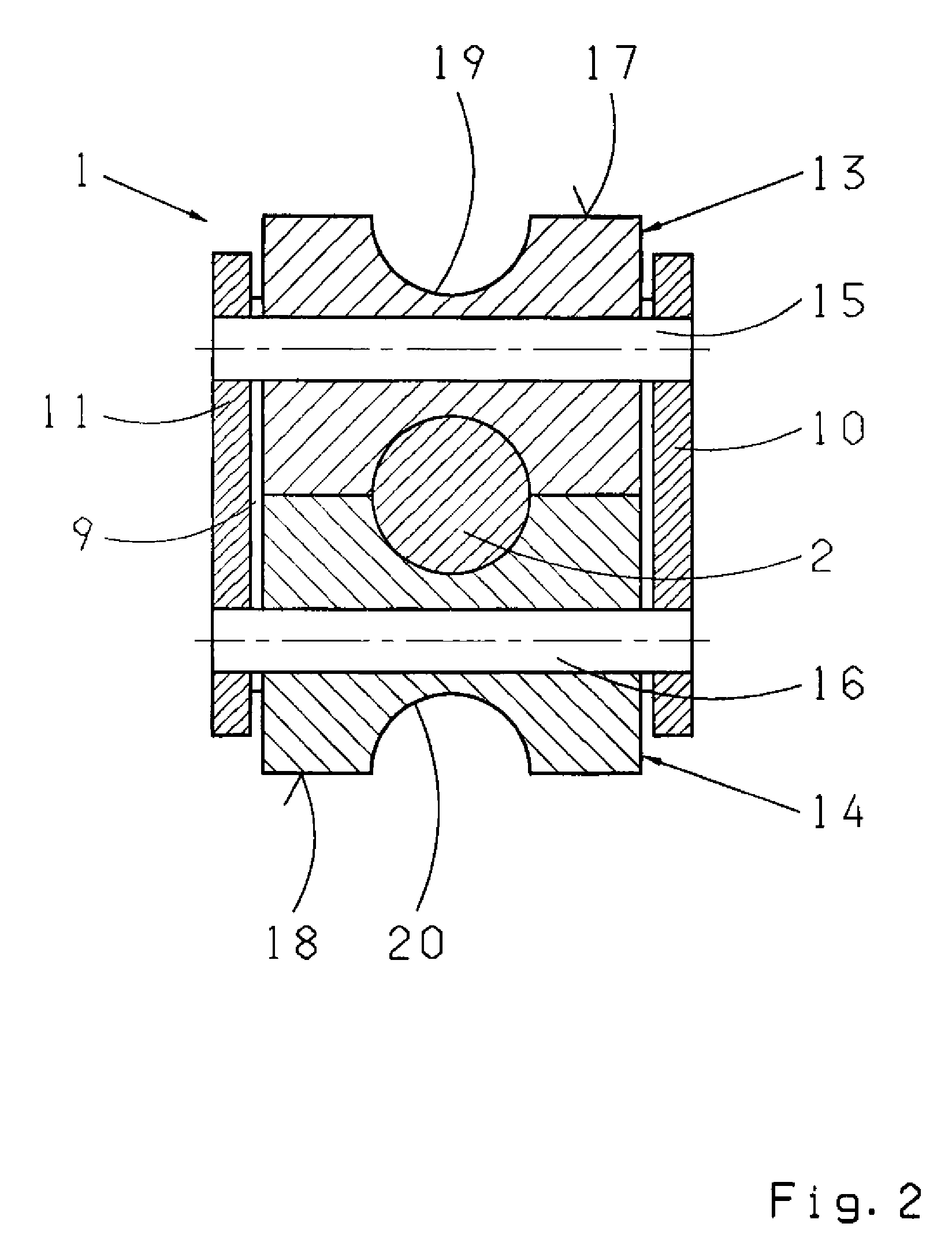
[0017]To be able to pass a positioning rod with a circular cross-section through the all-round grooves without interference, as a further advantageous feature of the invention, the first and the second all-round grooves form a conjoint, cross-section of essentially circular shape.

Problems solved by technology

The actuating carrier comprises several components with various connection points so the design is expensive and prone to malfunction.
Furthermore, the known actuating element takes up considerable structural space so that it cannot be used for axial pawl actuation or only so with difficulty.

Method used


Image

  • Actuating element for the parking lock of a transmission and parking lock for a transmission
  • Actuating element for the parking lock of a transmission and parking lock for a transmission
  • Actuating element for the parking lock of a transmission and parking lock for a transmission

Examples


Embodiment Construction

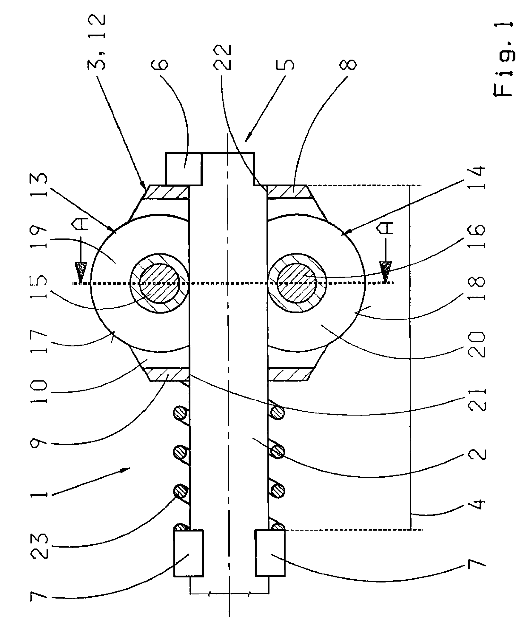
[0029]FIGS. 1 and 2, first, show an embodiment of the actuating element 1 for a parking lock of a transmission. The parking lock is described in more detail later with reference to FIGS. 3 and 4. The actuating element 1 comprises a positioning rod 2 and a roller carrier 3. The positioning rod 2 has a straight end section 4 at whose free end 5, a radially projecting first end-stop 6 and, at whose other end, are formed a radially projecting second end-stop 7.

[0030]The roller carrier 3 has a front wall 8, a rear wall 9 opposite the front wall 8 and two sidewalls 10, 11 opposite one another, which together form a housing 12 open at the top and bottom. Inside the roller carrier 3 are arranged a first roller 13 and a second roller 14. The first roller 13 is mounted to rotate on a first spindle 15 and the second roller 14 is mounted to rotate on a second spindle 16. The first and the second spindles 15, 16 are parallel to one another. As can be seen particularly clearly in FIG. 2, the two ...


PUM


Abstract

A transmission parking lock and an actuating element (1) for the parking lock. The actuating element includes a pull rod (2) and a roller carrier (3) on which are arranged a first roller (13) for rolling on a first rolling surface on the pawl of the parking lock and a second roller (14) for rolling on a second rolling surface on a guide element, such that the roller carrier (3) can be moved along a predetermined path in the longitudinal direction of the pull rod (2). The roller carrier (3) can move longitudinally on the pull rod (2).

Description

[0001]This application is a national stage completion of PCT / EP2007 / 056547 filed Jun. 29, 2007, which claims priority from German Application Serial No. 10 2006 030 998.7 filed Jul. 5, 2006.FIELD OF THE INVENTION[0002]The present invention concerns an actuating element for the parking lock of a transmission with a positioning rod and a roller carrier on which a first roller for rolling on a first rolling surface on the pivotable pawl of the parking lock and a second roller for rolling on a second rolling surface on a guide element are arranged so that the roller carrier can move along a predetermined path in the longitudinal direction of the positioning rod. The present invention also concerns a parking lock for a transmission having an actuating element of the type.BACKGROUND OF THE INVENTION[0003]From the prior art, various parking locks for automatic transmissions are known. DE 101 44 063 B4 describes a parking lock which comprises a pawl and a retaining ring on the drive output ...

Claims


Application Information

Patent Timeline
Patent Type & Authority Patents(United States)
IPC IPC(8): B60T1/06
CPCF16H63/3416F16H63/3425Y10T74/2107Y10T74/19637Y10T74/20177F16H63/34B60T1/00
Inventor REICHERT, HEINZ
Owner ZF FRIEDRICHSHAFEN AG
Learn More