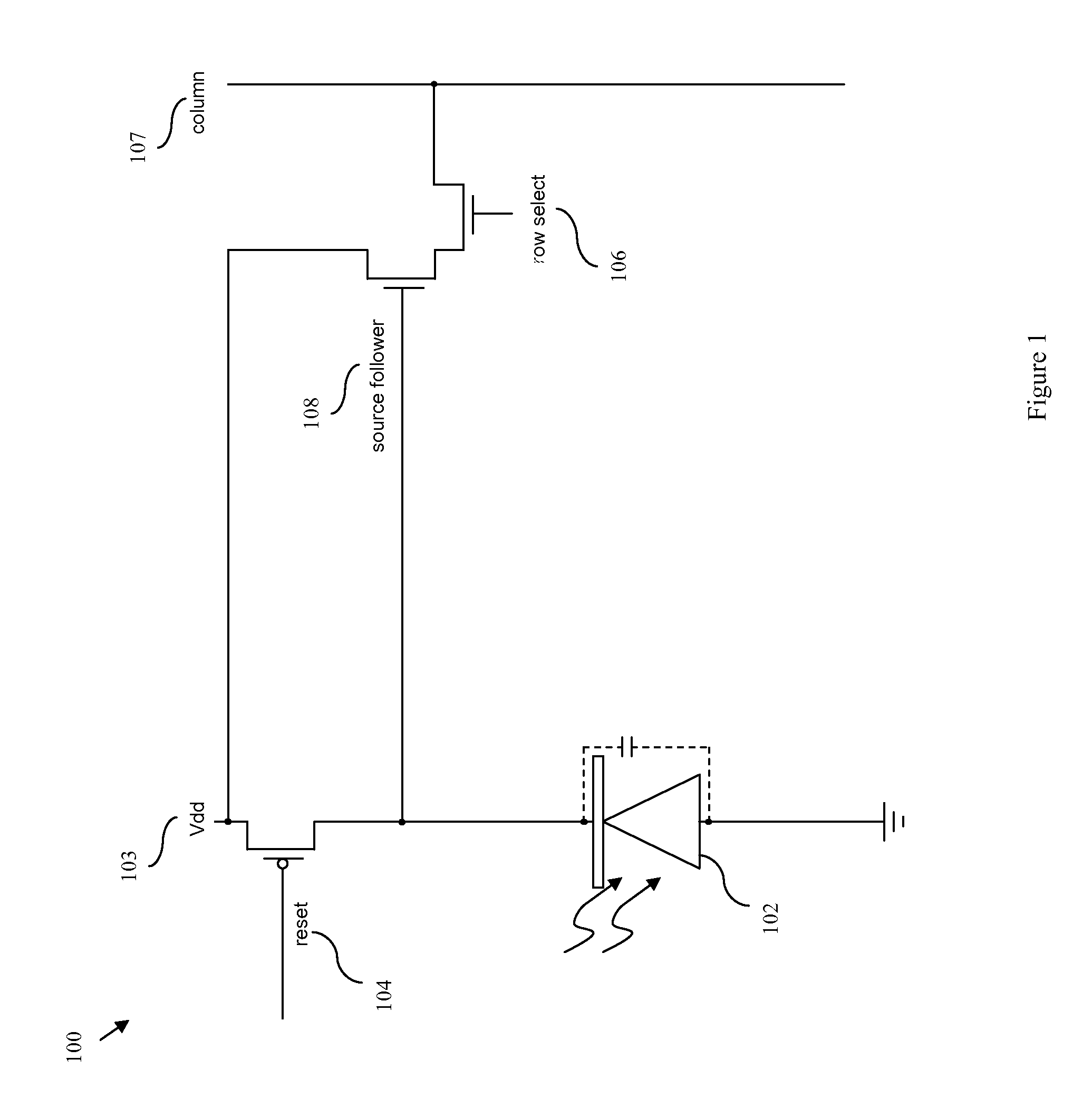
[0003]In view of the foregoing, disclosed herein are embodiments of a pixel imaging circuit that incorporates a standard photodiode. However, the imaging circuit is modified with a feedback loop to provide a first photo response over a first portion of the light sensing range (e.g., at a lower light intensity range) and a second reduced-sensitivity photo response over a second portion of the light sensing range (i.e., at a higher light intensity range), thereby extending the circuit's dynamic range of coverage. Also disclosed are embodiments of an associated imaging method and a design structure that is embodied in a machine readable medium and used in the imaging circuit design process.
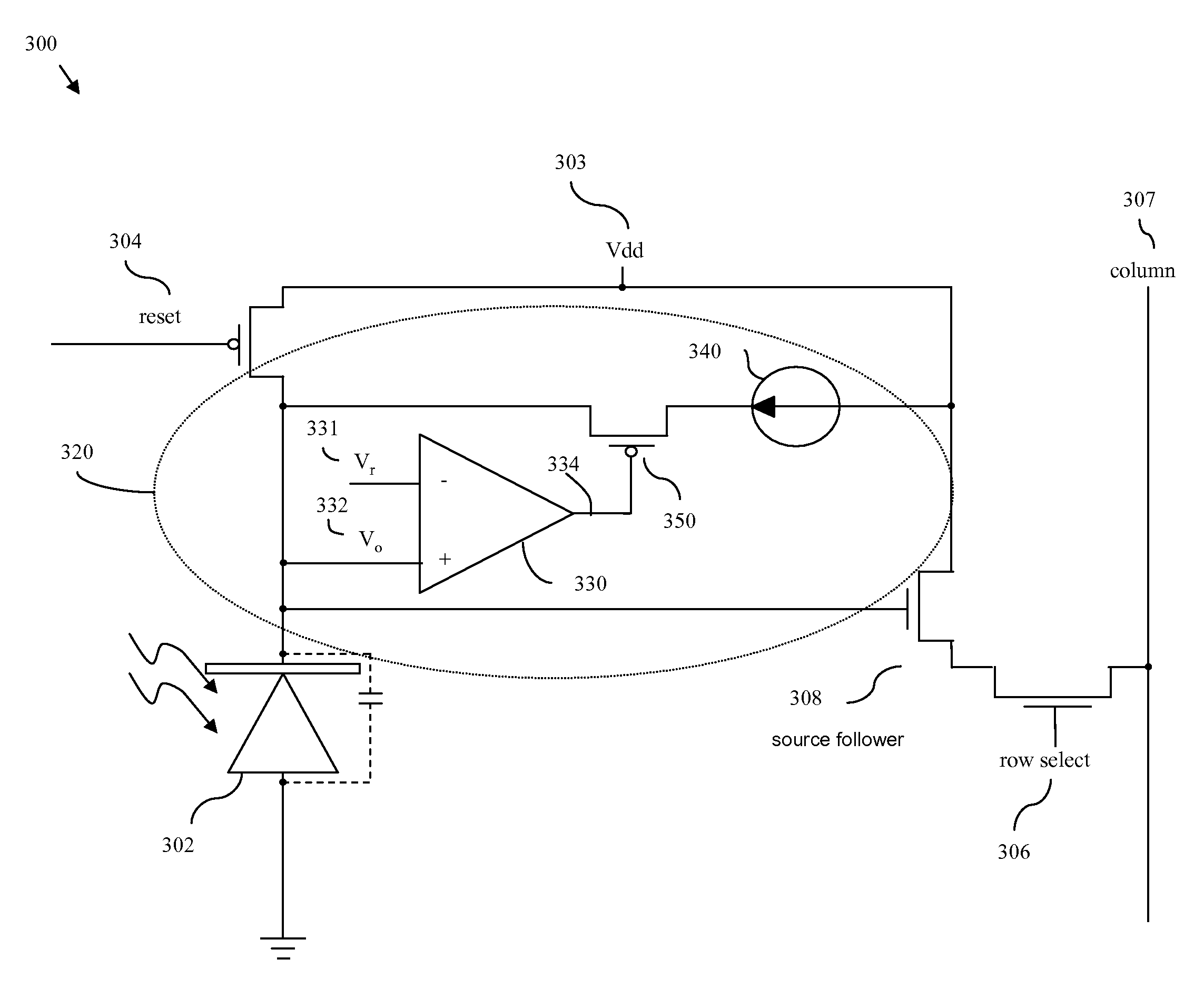
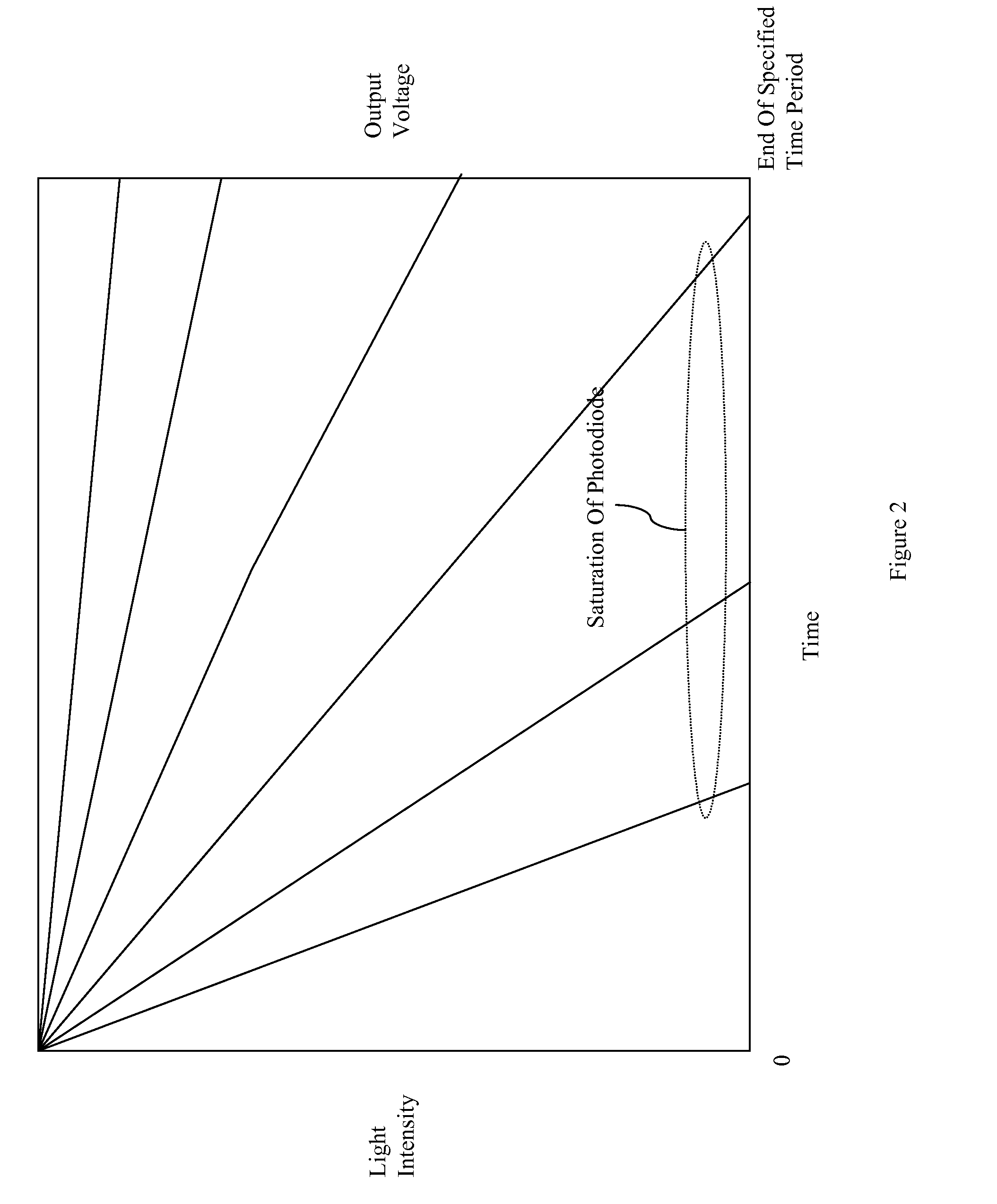
[0005]More specifically, the present imaging circuit incorporates a feedback loop that applies a constant current to the photodiode, only when the output voltage of the photodiode is below a predetermined reference voltage in order to reduce the sensitivity of the photodiode response at higher light intensity levels. To accomplish this, the feedback loop comprises a comparator electrically connected to the photodiode and to a predetermined reference voltage. The comparator is adapted to receive the electric current output from the photodiode and to compare the voltage of that electric current with the predetermined reference voltage. That is, the comparator is adapted to determine whether or not the output voltage from the photodiode is less than the predetermined reference voltage. The feedback loop further comprises a current source connected to the photodiode by a switch, which in turn is controlled by the output of the comparator. This switch is adapted to control the flow of a constant current from the current source to the photodiode. Specifically, if the switch is turned on a constant current will be supplied to the photodiode and if the switch remains off no current will be supplied to the photodiode. Thus, if the output voltage of the photodiode is determined by the comparator to be at or above the reference voltage, the switch will remain off preventing a constant current from flowing to the photodiode. Without the constant current, the photodiode will reduce the output voltage in response to the intensity of the light energy at a first rate (i.e., the photodiode will discharge at a first rate). However, if the output voltage of the photodiode is determined by the comparator to be below the reference voltage, the switch will turn on allowing a constant current to flow to the photodiode. With the constant current, the photodiode rate of discharge is reduced. Thus, the photodiode will reduce the output voltage in response to the intensity of the light energy at a second rate that is different from the first rate and, more specifically, that is less than the first rate. Consequently, the sensitivity of the photodiode is greater within a first range of light intensities (i.e., to lower intensity light) than within a second range of light intensities that is greater than the first range (i.e., to higher intensity of light). That is, the sensitivity of the photodiode is reduced with higher light intensities. This second rate prevents saturation of the photodiode within the second range of light intensities during the integration period and, thereby, extends the dynamic range of the imaging circuit.
[0006]In addition to the features described above, the photodiode can be configured such that the first rate is lower than the rate of discharge of the light energy. This will ensure that, once the switch is turned on by the comparator allowing current to flow to the photodiode, it will remain on. Furthermore, while the current applied to the photodiode by the feedback loop must be constant, the current source itself can be variable (i.e., it can be adapted to allow the constant current to be pre-set to a specified level, either manually or automatically, based on known lighting conditions or through light metering). Thus, the variable current source allows the second rate to be adjusted, as needed.
[0007]Also disclosed herein are embodiments of an associated imaging method. The method embodiments comprise converting light energy into electric current over an integration period. Specifically, a reset switch is activated to allow a supply voltage to charge a photodiode. The reset switch is then turned off and the photodiode is exposed to light energy, thereby discharging the photodiode and converting the light energy into electric current with the output voltage of the photodiode being inversely proportional to the intensity of that light energy. Next, the output voltage of the photodiode is compared to a predetermined reference voltage in order to determine whether the photodiode output voltage is less than the predetermined reference voltage. Then, when and only when the photodiode output voltage is less than the predetermined reference voltage, is a constant current applied to the photodiode. Without this constant current, the photodiode output voltage will be reduced in response to the intensity of the light energy at a first rate. However, with the constant current, the photodiode output voltage will be reduced in response to the intensity of the light energy at a second rate that is different from the first rate and, more specifically, that is less than the first rate. Consequently, the method provides for greater sensitivity within a first range of light intensities (i.e., to light of lower intensities) than within a second range of light intensities that is greater than the first range (i.e., to light of higher intensities). That is, the sensitivity of the photodiode is reduced with higher light intensities. This second rate prevents saturation of the photodiode within the second range of light intensities during the integration period.
[0008]The method embodiments can include several additional features. For example, method embodiments can include pre-selecting the photodiode so that the first rate is lower than a rate of discharge of the light energy to ensure that, once the constant current flows to the photodiode, the output voltage will remain below the predetermined reference voltage. The method embodiments can include automatically or manually pre-setting the constant current to a specified level based on known lighting conditions or through light metering, thereby allowing the second rate to be adjusted. Finally, after the integration period, a simple interpolation can be applied in order to normalize the output voltage in cases where it was reduced at the second rate.


