
Method and device for field quality testing of a magnetic resonance antenna

a magnetic resonance antenna and testing device technology, applied in the direction of measuring devices, magnetic measurements, instruments, etc., to achieve the effect of shortening the measurement time and increasing the measurement tim

Inactive Publication Date: 2012-02-14
SIEMENS HEALTHCARE GMBH
View PDF8 Cites 2 Cited by
  • Summary
  • Abstract
  • Description
  • Claims
  • Application Information

AI Technical Summary

Benefits of technology

[0009]An object of the present invention is to provide a simplified but nevertheless more certain method for field quality check and a testing device suitable for this purpose.

Problems solved by technology

Possible reasons for this are, for example, that the fuse normally provided for each antenna element has blown, [or] that the pre-amplifier belonging to the antenna element or a cable is defective.

Method used


Image

  • Method and device for field quality testing of a magnetic resonance antenna
  • Method and device for field quality testing of a magnetic resonance antenna
  • Method and device for field quality testing of a magnetic resonance antenna

Examples


Embodiment Construction

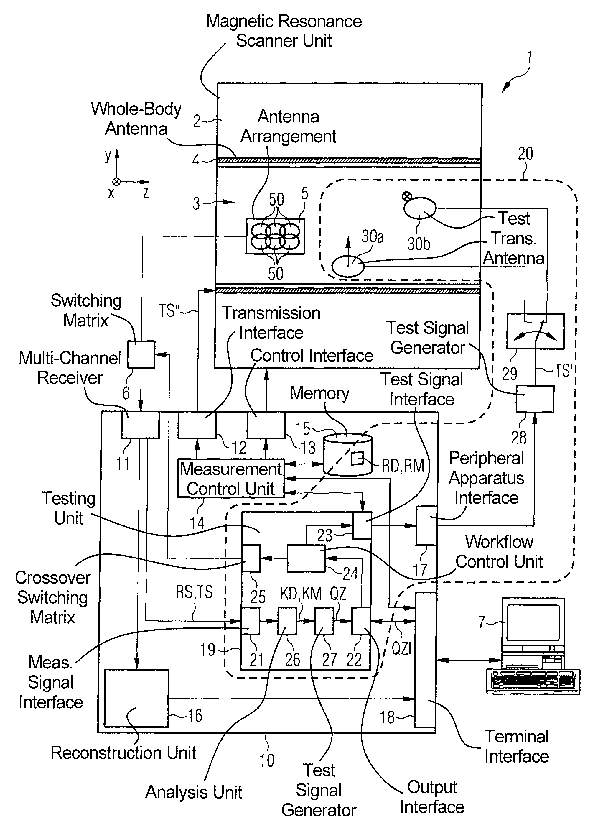
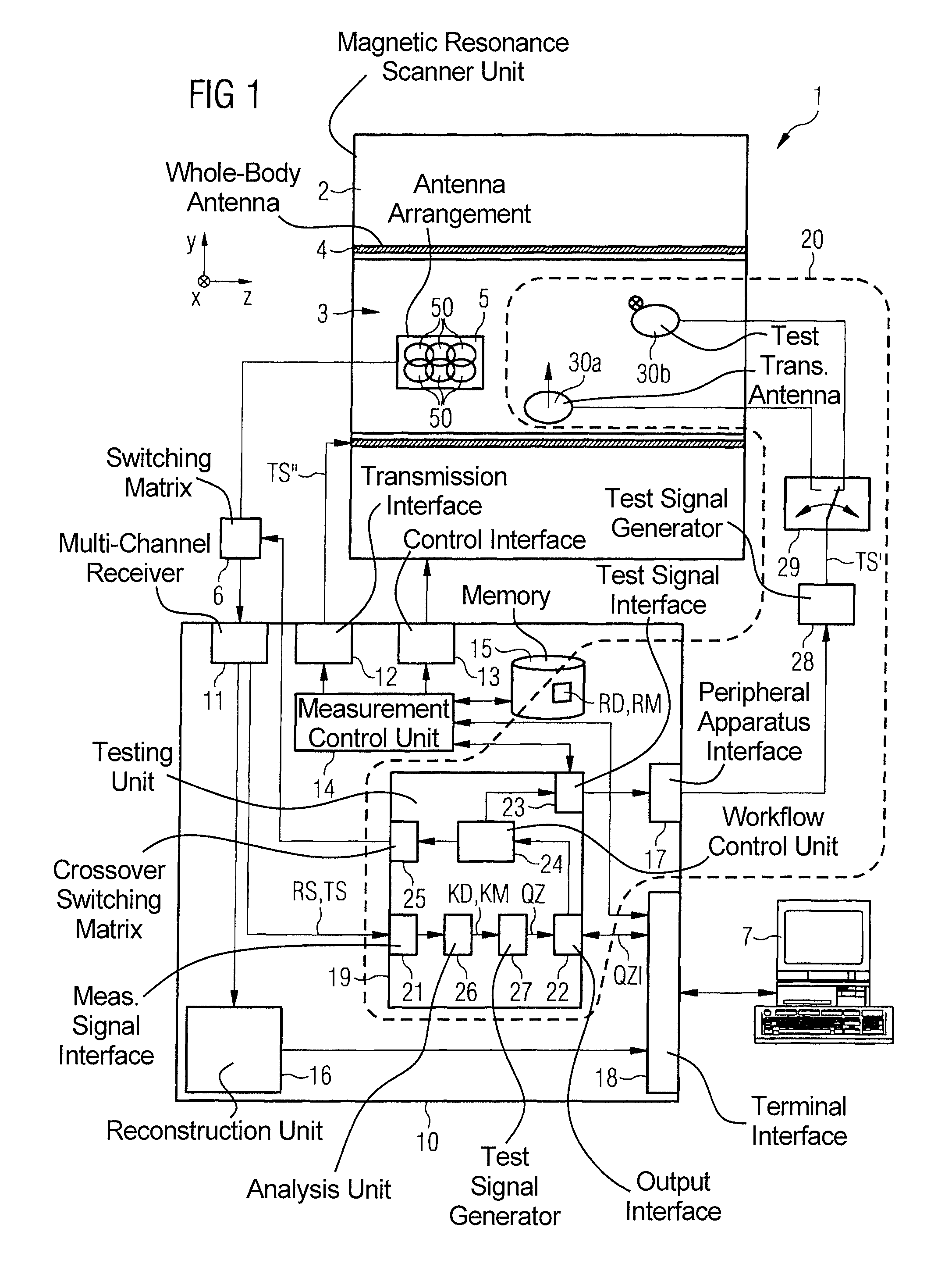
[0049]A magnetic resonance system 1 according to the invention is shown in a rough schematic illustration in FIG. 1.

[0050]The system includes the actual magnetic resonance scanner unit 2 in which an examination subject or a patient or test subject is placed on a patient bed (not shown) in a magnetic resonance measurement chamber or patient tunnel 3 during an examination. There is a number of components in this magnetic resonance scanner unit 2. These components include a basic magnetic field generation unit that generates an optimally homogenous basic magnetic field inside the patient tunnel 3. Furthermore, the magnetic resonance scanner unit 2 contains gradient coils with which a magnetic field gradient can be applied in a defined manner within the patient tunnel 3, as well as a whole-body antenna 4 with which radio-frequency fields can be emitted in the patient tunnel 3.

[0051]In addition to the aforementioned components (of which only the whole-body antenna 4 is schematically show...


PUM


Abstract

In a method and device for field quality testing of a magnetic resonance antenna arrangement of a magnetic resonance system composed of multiple antenna elements, a test signal is fed into the respective antenna elements by a transmission antenna and the test signal, or a noise signal that occurs with no signal fed to the respective antenna elements, is determined at a receiver unit for each of at least some of the individual antenna elements. The noise received noise signals and / or test signals are analyzed with regard to specific characteristic data and a quality state of the magnetic resonance antenna arrangement is determined based thereon.

Description

BACKGROUND OF THE INVENTION[0001]1. Field of the Invention[0002]The present invention concerns a method and a testing device for field quality testing of a magnetic resonance antenna arrangement of a magnetic resonance system, the magnetic resonance antenna arrangement being formed of multiple antenna elements. As used herein, “field quality testing” means testing a quality testing (in particular error checking) of the magnetic resonance antenna arrangement on location at the operating (installation) site, in particular in a situation located in the magnetic resonance measurement (data acquisition) chamber of the magnetic resonance system. Moreover, the invention concerns a magnetic resonance system with such a testing device and a magnetic resonance antenna arrangement.[0003]2. Description of the Prior Art[0004]Magnetic resonance tomography is a widespread method for acquisition of images of the inside of a body. In this method the body to be examined is exposed to a relatively hig...

Claims


Application Information

Patent Timeline
Patent Type & Authority Patents(United States)
IPC IPC(8): G01V3/00
CPCG01R33/3415G01R33/36G01R33/3642G01R33/288G01R33/543
Inventor BIBER, STEPHAN
Owner SIEMENS HEALTHCARE GMBH
Learn More