
Trim retention spring and method for recessed lighting fixtures

a technology for recessed lighting and retention springs, which is applied in the field of recessed lighting fixtures, can solve the problems of not having the trim may not have the correct length, angular orientation, or shape to correctly engage the friction clip, etc., and achieves the effect of avoiding reinstallation of trims

Active Publication Date: 2012-01-17
HUBBELL LIGHTING INC
View PDF29 Cites 21 Cited by
  • Summary
  • Abstract
  • Description
  • Claims
  • Application Information

AI Technical Summary

Benefits of technology

The spring clip system provides positive trim retention with automatic adjustment, ensuring the trim is flush and aligned with the ceiling, allowing for tool-less installation and easy removal, while accommodating imperfect fixture housing installations and existing trim designs.

Problems solved by technology

In certain situations, the friction clip is not an ideal retention method due to a number of factors.
The trim may not have the correct length, angular orientation, or shape to correctly engage the friction clip.
The pressure required to engage and adequately retain the trim causes dents or deformations in the trim, ruining the optical and aesthetic properties designed to be provided by the trim.
Even if the friction clip and trim engage and work properly, the installed orientation is not ideal.
The friction clip and trim do not work as intended because of slight deviations in the installation such as the fixture housing not being flush with the ceiling surface, installed at an angle, or installed in a ceiling slightly thicker than the intended design of the product.
With some friction clips, this removal and replacement process is very difficult and tends to degrade both the trim and friction clip.

Method used


Image

  • Trim retention spring and method for recessed lighting fixtures
  • Trim retention spring and method for recessed lighting fixtures
  • Trim retention spring and method for recessed lighting fixtures

Examples


Embodiment Construction

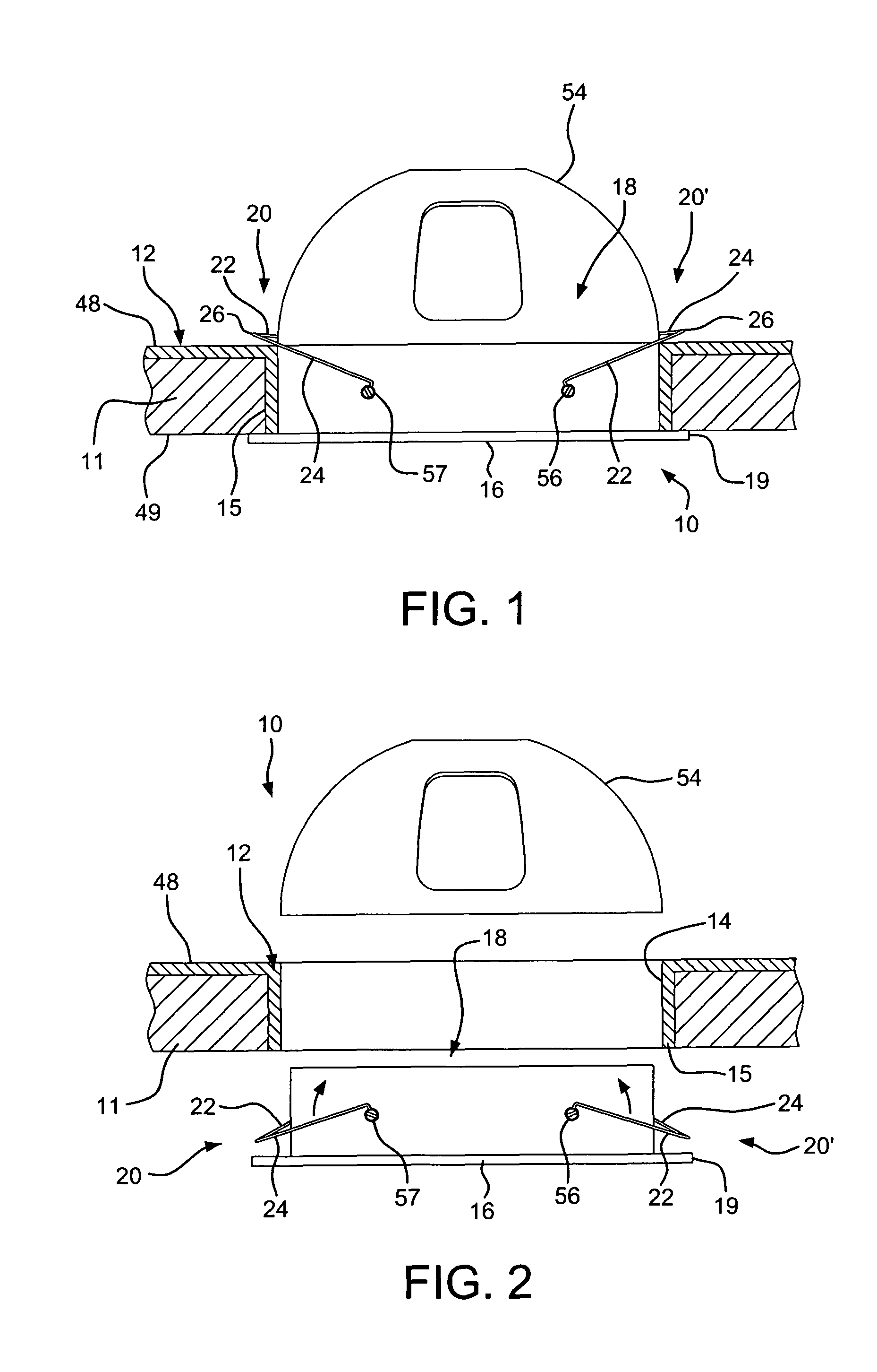
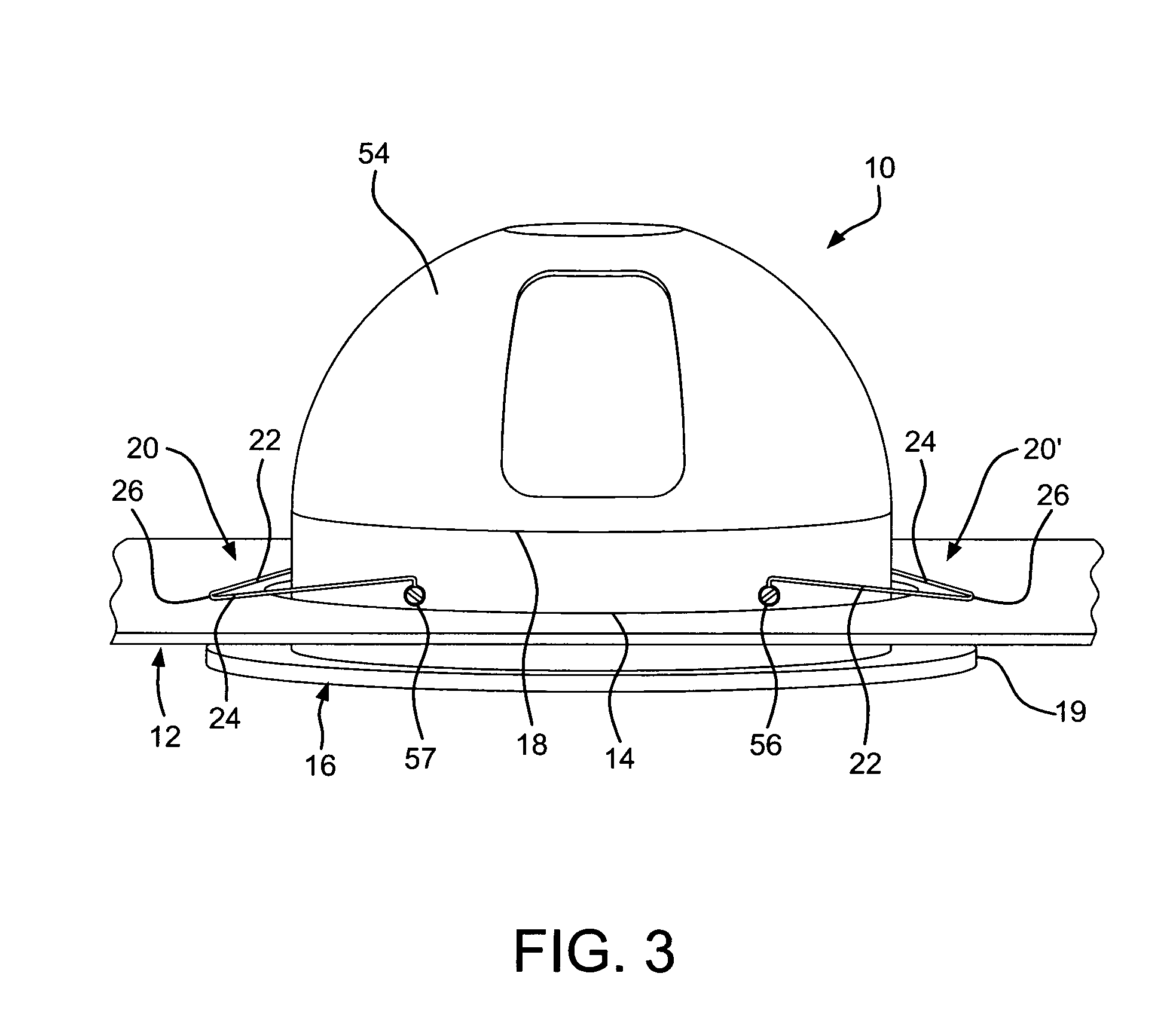
[0041]The present invention is directed to a lighting fixture and a trim ring installed with a spring retention clip that can be easily assembled to the lighting fixture while providing positive trim retention. The invention is also directed to a lighting fixture and trim ring that can be easily assembled without the use of tools by providing a spring member coupled to the trim for a downward spring force to couple the trim to the lighting fixture.

[0042]Turning to the first embodiment illustrated in FIGS. 1-8, a lighting fixture 10 includes a ceiling pan 12 with an opening 14 in a ceiling 11, a top surface 48, and a downwardly extending collar 15 for receiving part of the lighting fixture 10 therein and directing light to a target area. The opening 14 extends between the top surface 48 and bottom surface 49. A trim 16 is received in the opening 14. The trim 16 includes a ring-shaped side wall 18 or trim ring 18 extending upwardly from an outwardly extending flange 19. In the embodim...


PUM


Abstract

A lighting fixture is provided that includes a ceiling pan having an opening with a trim received therein. The trim includes a ring with a spring clip attached thereto. The spring clip includes first and second legs having a first end joined at an apex and second free end opposite the first end. The second free ends are fixed to the trim to bias the spring clip in a downward direction to engage a top surface of the ceiling pan and bias the trim in an upward direction toward the ceiling pan. In one embodiment, the ends of the spring clip are fixed to the trim by a screw. In another embodiment, the spring clip is a torsion spring engaging the trim and includes first and second legs with a portion extending therefrom and received in an aperture in the trim. The ends are oriented at an inclined angle with respect to the legs such that when the legs are attached to the trim, the legs are biased in a downward direction with respect to the ceiling pan. The torsion spring clip can be retrofit to the trim ring.

Description

FIELD OF THE INVENTION[0001]The present invention is directed to a lighting fixture having a trim retention device in the form of a spring clip. The spring clip includes first and second legs having a first end joined at an apex and second free ends fixed to a trim. The apex engages a top surface of a ceiling pan and the spring clip applies a downward force to pull the trim ring into the opening of the ceiling pan and towards the bottom surface of the ceiling pan. In one embodiment, a torsion spring clip includes first and second legs each having an extension or free end portion bent at an inclined angle to impart a downward force of the torsion spring clip to pull the trim ring toward the ceiling pan when the end portion is attached to the trim.BACKGROUND OF THE INVENTION[0002]Conventional methods of trim retention involve mounting a friction clip to a fixture housing, or trim, which provides an interference fit during installation. In certain situations, the friction clip is not a...

Claims


Application Information

Patent Timeline
Patent Type & Authority Patents(United States)
IPC IPC(8): F21V15/00F21S8/00
CPCF21V21/04
Inventor WILCOX, SHAWN
Owner HUBBELL LIGHTING INC
Learn More