Method and apparatus for measuring electrical impedance of thin fluid films

a thin fluid and electrical impedance technology, applied in the field of electric impedance, can solve the problems of inability to overcome the unstable and delicate nature of thin fluid samples, hampered conventional measurement methodologies,

Inactive Publication Date: 2012-01-10
NAVY THE UNITED STATES OF AMERICA SEC OF THE
View PDF10 Cites 4 Cited by
  • Summary
  • Abstract
  • Description
  • Claims
  • Application Information

AI Technical Summary

Problems solved by technology

Conventional measurement methodologies are hampered by their inability to overcome the unstable and delicate nature of their thin fluid samples, which are akin to easily burst bubbles.

Method used


Image

  • Method and apparatus for measuring electrical impedance of thin fluid films
  • Method and apparatus for measuring electrical impedance of thin fluid films
  • Method and apparatus for measuring electrical impedance of thin fluid films

Examples


Embodiment Construction

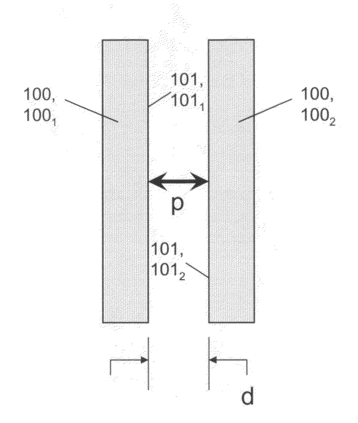
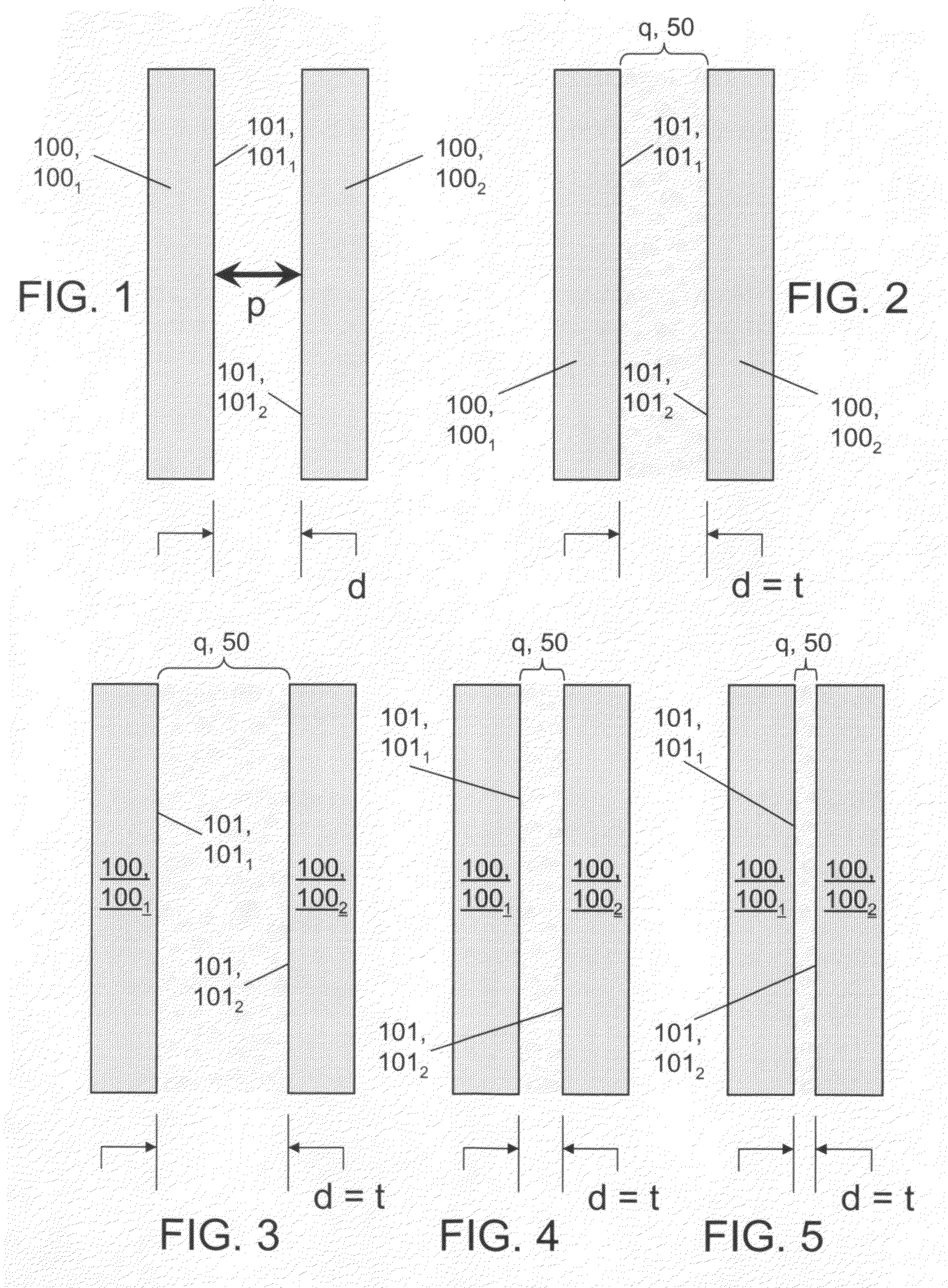
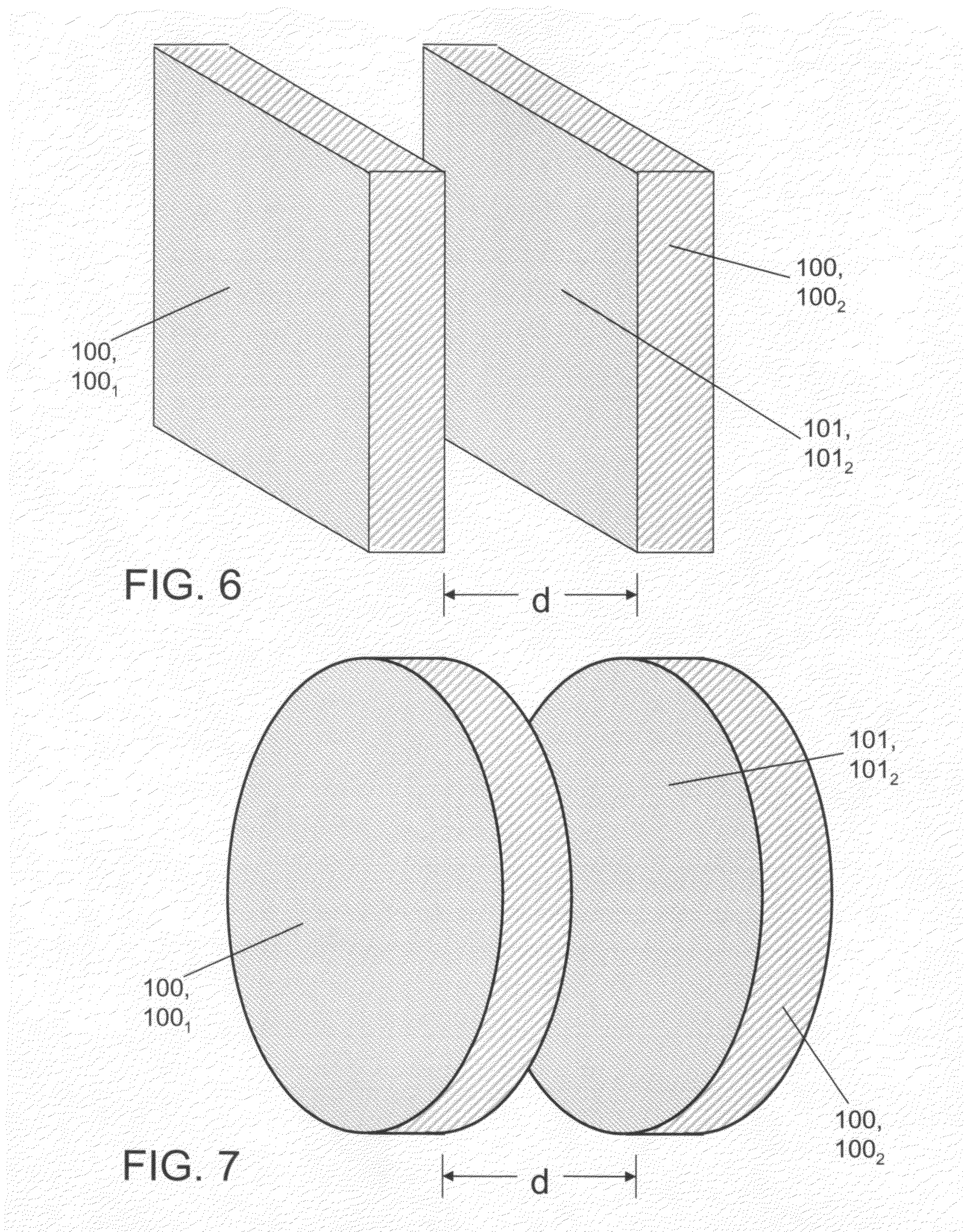
[0028]Referring now to FIG. 1 through FIG. 5, two presses 100, viz., presses 1001 and 1002, are spaced apart from each other so that their respective flat (planar) surfaces 101 are separated from each other by a distance d. Each press 100 is an electrically nonconductive structure, and is preferably characterized by low electrical permittivity. Suitable electrically nonconductive materials for inventive presses 100 include, but are not limited to, those belonging to the following categories: plastics; ceramics; glass; solid resins; composites.

[0029]Press 1001 has a flat surface 1011; press 1002 has a flat surface 1012. Flat surfaces 1011 and 1012 are parallel to and opposite each other. Distance d is the perpendicular distance between the parallel flat surfaces 1011 and 1012, respectively, of the two opposing presses 1001 and 1002. As shown in FIG. 2 through FIG. 5, flat surfaces 1011 and 1002 delimit therebetween a quantity of fluid, fluid quantity q, which represents the fluid tes...


PUM


Abstract

According to typical inventive practice, the relative positioning of two press members is mechanically adjustable so that their respective flat surfaces remain parallel at selectively closer or further distances apart. During immersion or partial immersion of the two press members in a fluid of interest, a fluid sample is bounded by the two opposing flat surfaces. The present invention can thus achieve small thicknesses of its fluid samples, which represent “thin fluid films” suitable for measurement of one or more electrical characteristics (e.g., impedance, or impedance-related characteristics such as permittivity). Data acquisition can be performed by generating electrical pulses and receiving data signals from probes contiguous with the fluid sample. Measurements can be taken of fluid samples characterized by varying thicknesses and / or varying pressures. As distinguished from conventional methodologies, which are beset with “bubble-bursting” transience and fragility, the inventive methodology provides thin fluid films that are stable and robust.

Description

CROSS-REFERENCE TO RELATED APPLICATIONS[0001]This application claims the benefit of U.S. provisional patent application No. 61 / 132,336, hereby incorporated herein by reference, filing date 11 Jun. 2008, invention title “Method and Apparatus for Measuring Electrical Impedance of Thin Fluid Films,” sole inventor Jerry Rosson Smith, Jr.BACKGROUND OF THE INVENTION[0002]The present invention relates to electrical impedance, more particularly to methods and apparatuses for measuring the electrical impedance of a thin film of fluid.[0003]Electrical impedance, typically designated “Z” and expressed in ohms, is the amount of resistance of an electrical circuit to current flow upon the provision of a voltage across a pair of terminals of the electrical circuit. Basically, the impedance of the electrical circuit is the ratio of the voltage across the terminals to the current flow between the terminals. Impedance in direct current (DC) circuits and alternating current (AC) circuits are analogou...

Claims


Application Information

Patent Timeline
Patent Type & Authority Patents(United States)
IPC IPC(8): G01R27/00
CPCG01R27/22
Inventor SMITH, JR., JERRY ROSSON
Owner NAVY THE UNITED STATES OF AMERICA SEC OF THE
Why Eureka
Try Eureka