
Battery pack and internal component arrangement within the battery pack for cordless power tool system

a technology of battery pack and battery cell, which is applied in the manufacture of cell components, portable power-driven tools, and final products. it can solve the problems of increasing fabrication costs, affecting the mechanical retention of all of these components and battery cells, and unable to provide an adequate support structure/housing

Active Publication Date: 2012-01-10
BLACK & DECKER INC
View PDF12 Cites 1219 Cited by
  • Summary
  • Abstract
  • Description
  • Claims
  • Application Information

AI Technical Summary

Problems solved by technology

Current battery pack designs, such as those designed for cordless power tools and associated chargers of a cordless power tool system, do not typically provide an adequate support structure / housing to mechanically retain all of these components and the battery cells.
A bad weld can result in an open-circuited battery pack, which can be detected by an end of line tester and either scrapped or re-worked, increasing fabrication cost.
A marginal weld could fail in the field, either causing an open circuited pack or a high-impedance pack.
The manufacturing process of locating and restraining the multitude of straps needed for fabricating an individual battery pack can be difficult, requiring additional fixtures and cost.
This manufacturing technique may cause residual stresses on the weld joints.
During operating of the pack in a system, such as when attached to a cordless power tool, and upon operation-induced vibration and / or accidental dropping of the tool, these weld joints are more likely to fail because of residual stresses introduced during the assembly of the internal components within the pack housing.
Because this information is gathered from different locations within the battery pack, the wire-up of these conductors can pose a challenge to manufacturers.
Using thin gage wire, however, presents challenges in a power tool environment.
A power tool battery pack can experience high vibration in operation, such as during operation of a cordless reciprocating saw as well as severe mechanical shock, such as a user dropping a tool off of a multistory building.
These scenarios are likely to lead to failure of thin gage wire that is soldered or ultrasonically welded (or otherwise rigidly attached) to the cells.

Method used


Image

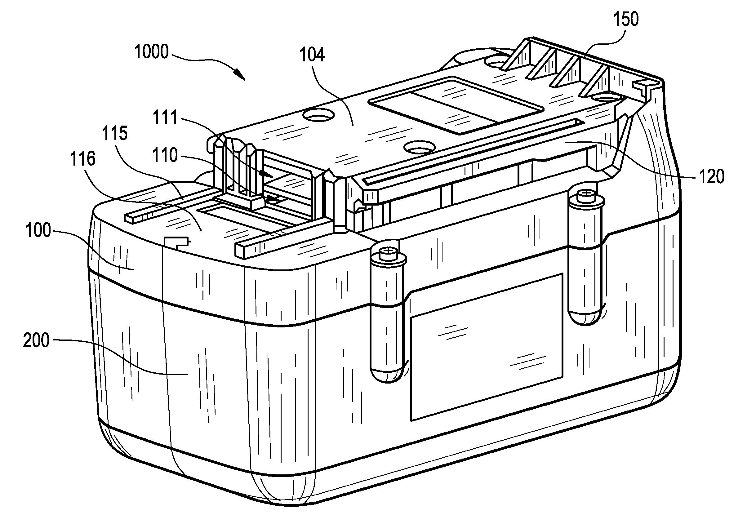
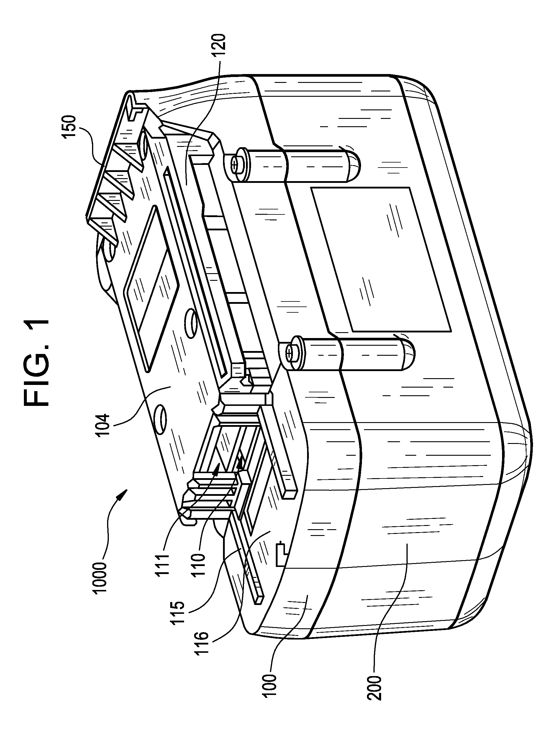
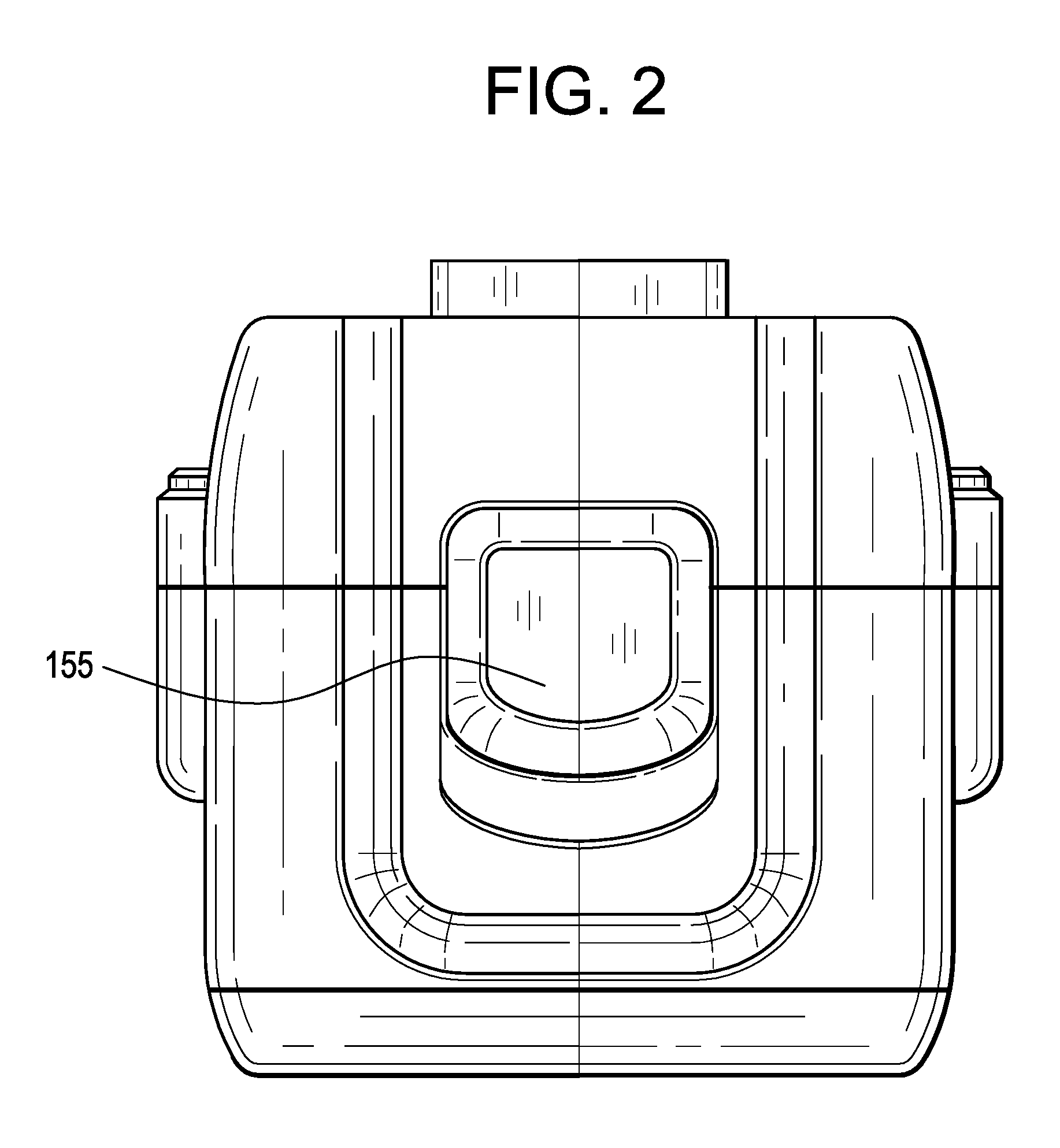
  • Battery pack and internal component arrangement within the battery pack for cordless power tool system
  • Battery pack and internal component arrangement within the battery pack for cordless power tool system
  • Battery pack and internal component arrangement within the battery pack for cordless power tool system

Examples


Embodiment Construction

[0035]With general reference to the drawings, a system of cordless power tools constructed in accordance with the teachings of example embodiments of the present invention is illustrated. Example cordless power tools of the system are shown to include, by way of examples only, a circular power saw 10 (FIG. 14), a reciprocating saw 20 (FIG. 15) and a drill 30 (FIG. 16). The tools 10, 20 and 30 each may include a conventional DC motor (not shown) adapted to be powered by a power source having a given nominal voltage rating.

[0036]Tools 10, 20 and 30 may be driven by a removable power source having a nominal voltage rating of at least 18 volts. It will become evident to those skilled that the present invention is not limited to the particular types of tools shown in the drawings nor to specific voltages. In this regard, the teachings of the present invention may be applicable to virtually any type of cordless power tool and any supply voltage.

[0037]With continued reference to the drawin...


PUM

PropertyMeasurementUnit
voltage ratingaaaaaaaaaa
heightaaaaaaaaaa

Abstract

An internal component arrangement within a battery pack housing having multiple cells and adapted for cordless power tools may provide desired mechanical support to constrain the cells. The housing with internal component arrangement is configured to route sensing wires from the cells to an electronics module of the pack.

Description

PRIORITY STATEMENT[0001]This application claims the benefit under 35 U.S.C. §119(e) to the following U.S. Provisional Patent Application Ser. No. 60 / 731,269, filed Oct. 31, 2005 to Daniel J. White et al. and entitled “BATTERY PACK FOR CORDLESS POWER TOOLS”, Ser. No. 60 / 731,486 filed Oct. 31, 2005 to Steven J. Phillips et al. and entitled “BATTERY PACK INTERNAL COMPONENT ARRANGEMENT”; and Ser. No. 60 / 836,396 filed Aug. 8, 2006 to Steven J. Phillips et al. and entitled “WELD STRAP IMPROVEMENTS FOR BATTERY CELLS”. The entire contents of each of these provisional applications are hereby incorporated by reference herein.BACKGROUND[0002]1. Field[0003]Example embodiments in general relate to a battery pack configured for powering tools of a cordless power tool system having an arrangement of internal components within a housing thereof, to an internal component arrangement for a battery pack and to a methodology for arranging the internal components within the battery pack.[0004]2. Descrip...

Claims


Application Information

Patent Timeline
Patent Type & Authority Patents(United States)
IPC IPC(8): H01M2/10H01M50/516H01M50/522H01M50/526H01M50/569
CPCB25F5/02H01M2/105H01M2/204H01M10/4207H01M10/5004H01M10/5014H01M10/5073H01M10/482Y10T29/49108H01M10/6235H01M10/6566H01M10/613Y02E60/10H01M50/213Y02P70/50H01M50/522H01M50/526H01M50/516H01M50/569
Inventor PHILLIPS, STEVEN J.WHITE, DANIEL J.CASALENA, ADAM M.KUEHNE, BRENT A.BAILEY, JR., R. ROBYROBERTS, JR., MICHAEL W.MARCINKOWSKI, ROBERT J.BOWERS, MICHELLE L.
Owner BLACK & DECKER INC
Learn More