
Printer with a touch panel

a touch panel and printer technology, applied in the field of printers, can solve the problems of reducing the efficiency of repairing and maintenance, time waste, etc., and achieve the effect of convenient and convenient storage and convenient repair and maintenan

Active Publication Date: 2012-01-03
EVEN SYST
View PDF13 Cites 0 Cited by
  • Summary
  • Abstract
  • Description
  • Claims
  • Application Information

AI Technical Summary

Benefits of technology

[0007]The main objective of the invention is to provide a printer that has a base, a touch panel and a printing module mounted detachably on the base. The printing module may be detached easily and conveniently from the base easily for repair and maintenance.

Problems solved by technology

Because the printer is incorporated with the touch panel ordering / checkout machine, repairing the printer requires disassembly of the touch panel, which is time wasting and lowers repairing efficiency.

Method used


Image

  • Printer with a touch panel
  • Printer with a touch panel
  • Printer with a touch panel

Examples


Embodiment Construction

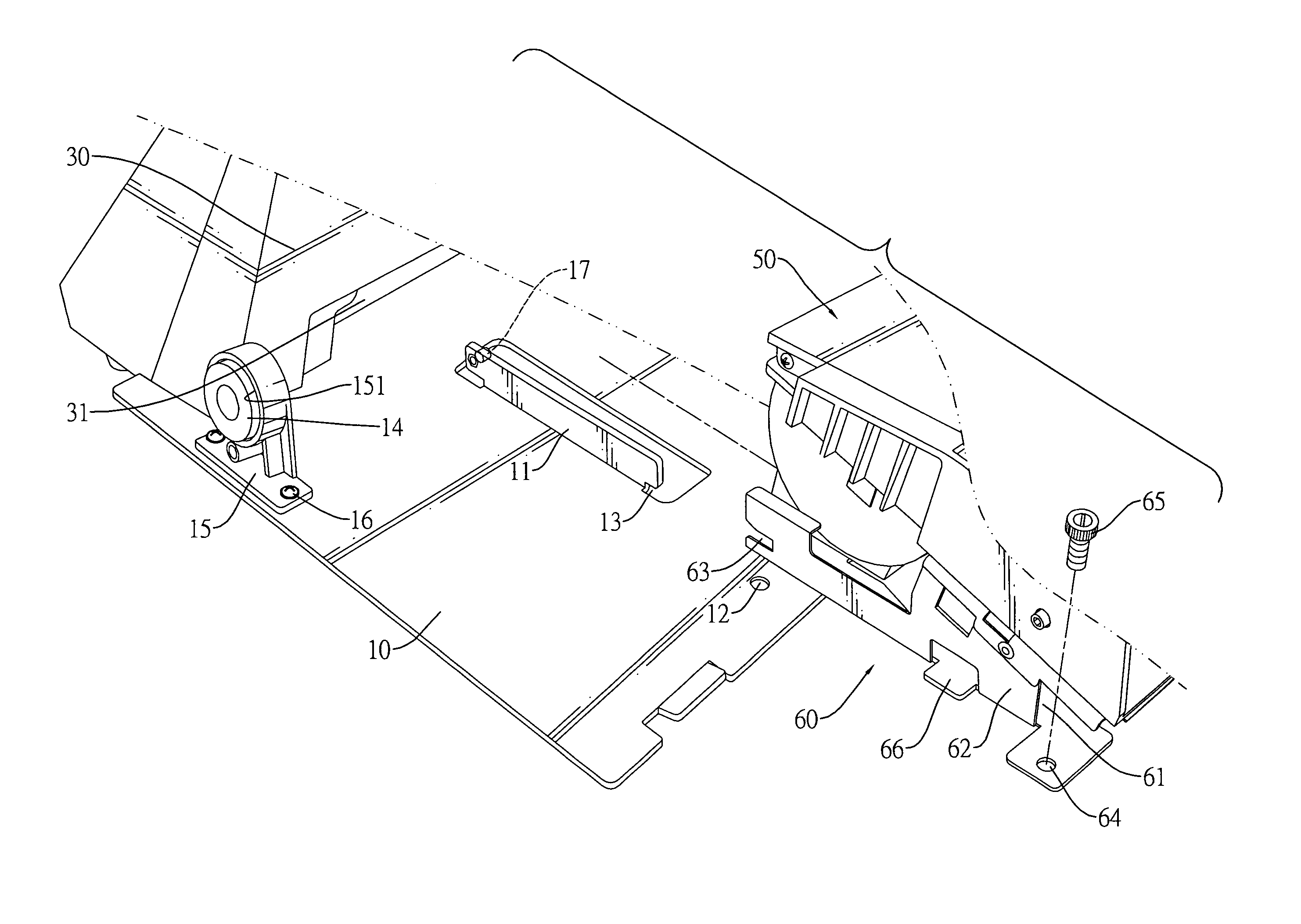
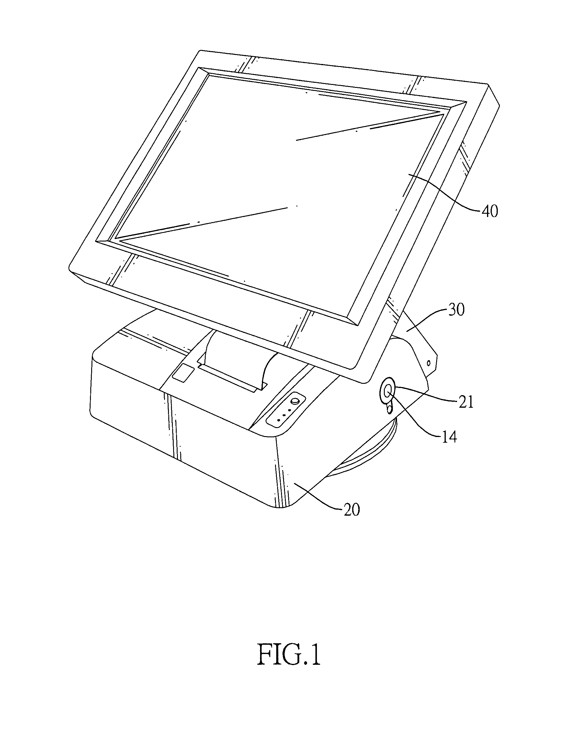
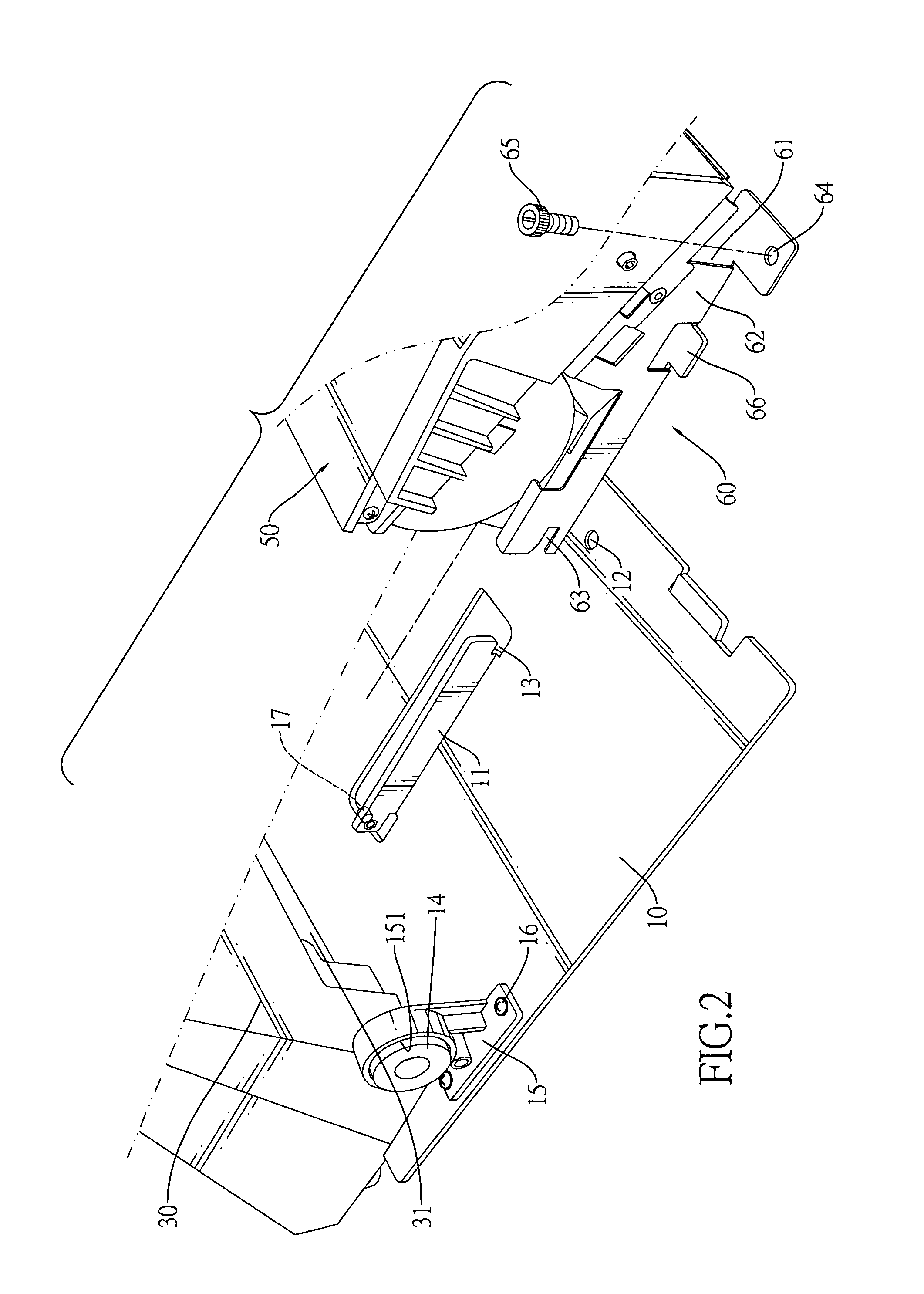
[0017]With reference to FIGS. 1 to 3, a printer in accordance with the present invention comprises a base (10), a cover (20), a touch panel (40), a printing module (50) and a detachable bracket (60).

[0018]The base (10) has a front, a rear, a top surface and two mounting rails (11) and may further have two pin brackets (15), two retractable locking pins (14), multiple fastening holes (12) and a supporting bracket (30).

[0019]The mounting rails (11) are mounted oppositely on the top surface of the base (10) and are parallel to each other. Each mounting rail (11) has a front end, a rear end, an inside, an outside, an engaging slot (13) and an engaging protrusion (17). The engaging slot (13) is defined in the front end. The engaging protrusion (17) is formed on and protrudes transversely from the inside.

[0020]The pin brackets (15) are mounted oppositely on the top surface of the base (10). Each pin bracket (15) may be fastened on the top surface through multiple fasteners (16) such as bo...


PUM


Abstract

A printer has a base, a cover, a touch panel, a printing module and a detachable bracket. The base has two mounting rails. Each mounting rail has an engaging slot and an engaging protrusion. The cover is mounted detachably on the base. The touch panel is mounted on the base. The printing module is mounted detachably on the base and covered by the cover. The detachable bracket is mounted securely on the printing module and has a bottom plate and two opposite side plates. Each side plate has an engaging tab and an engaging notch detachably engaging the engaging slot and protrusion of a corresponding mounting rail. The printer with the mounting rails and detachable bracket allows the printing module to be repaired independently without disassembling the touch panel.

Description

BACKGROUND OF THE INVENTION[0001]1. Field of the Invention[0002]The present invention relates to a printer, and more particularly to a printer that has a base, a touch panel and a printing module mounted detachably on the base. The printing module may be detached easily and conveniently from the base easily for repair and maintenance.[0003]2. Description of Related Art[0004]Ordering / checkout machines are commonly electronic devices used on counters in restaurants, department stores, supermarkets and grocery stores for ordering dishes and paying. A conventional ordering / checkout machine has a monitor and a keyboard for inputting orders therein. An improved ordering / checkout machine with a touch panel, which is more compact, has been developed recently so that a user may quickly input an order or goods information into the ordering / checkout machine on through the touch panel. Accordingly, working efficiency is increased to prevent customers intending to pay from waiting in a long queu...

Claims


Application Information

Patent Timeline
Patent Type & Authority Patents(United States)
IPC IPC(8): G07G1/00G03G15/00
CPCB41J3/36B41J3/445G03G15/5016G03G21/1661G03G2221/1651G03G2221/1687
Inventor TIANG, SEE-HINGSINGGIH, KHAIRIL
Owner EVEN SYST
Learn More