Moving-coil planar speaker
a planar speaker and moving coil technology, applied in the field of loudspeakers, can solve the problems of speaker thereby suffering a less satisfactory low-frequency performance, speaker's dynamic range being seriously affected, and the driver not being able to exert enough driving for
- Summary
- Abstract
- Description
- Claims
- Application Information
AI Technical Summary
Benefits of technology
Problems solved by technology
Method used
Image
Examples
first embodiment
[0031]As shown in FIGS. 5, 6, and 7, a planar speaker according to the present invention mainly contains a frame 11, a diaphragm 12, a driver 13, two suspension elements 14, and a surround 15. The frame 11 has a flat rectangular shape and the surround 15 is positioned between the circumference of a front opening of the frame 11 and the edge of the diaphragm 12. The diaphragm 12 is thereby suspended in the front opening of the frame 11 by the surround 15. The surround 15, on one hand, suppresses the vibration of the diaphragm 12 at its edge and, on the other hand, prevents the sound waves at either side of the diaphragm 12 from interfering with each other. The driver 13 is positioned in the center of the frame 11 behind the diaphragm 12. A voice coil of driver 13 is attached to a back surface of the diaphragm 12 so that a back-and-forth movement of the coil would cause the diaphragm 12 to vibrate and to produce sound waves.
[0032]Two beams 112 are arranged in parallel along a back ope...
third embodiment
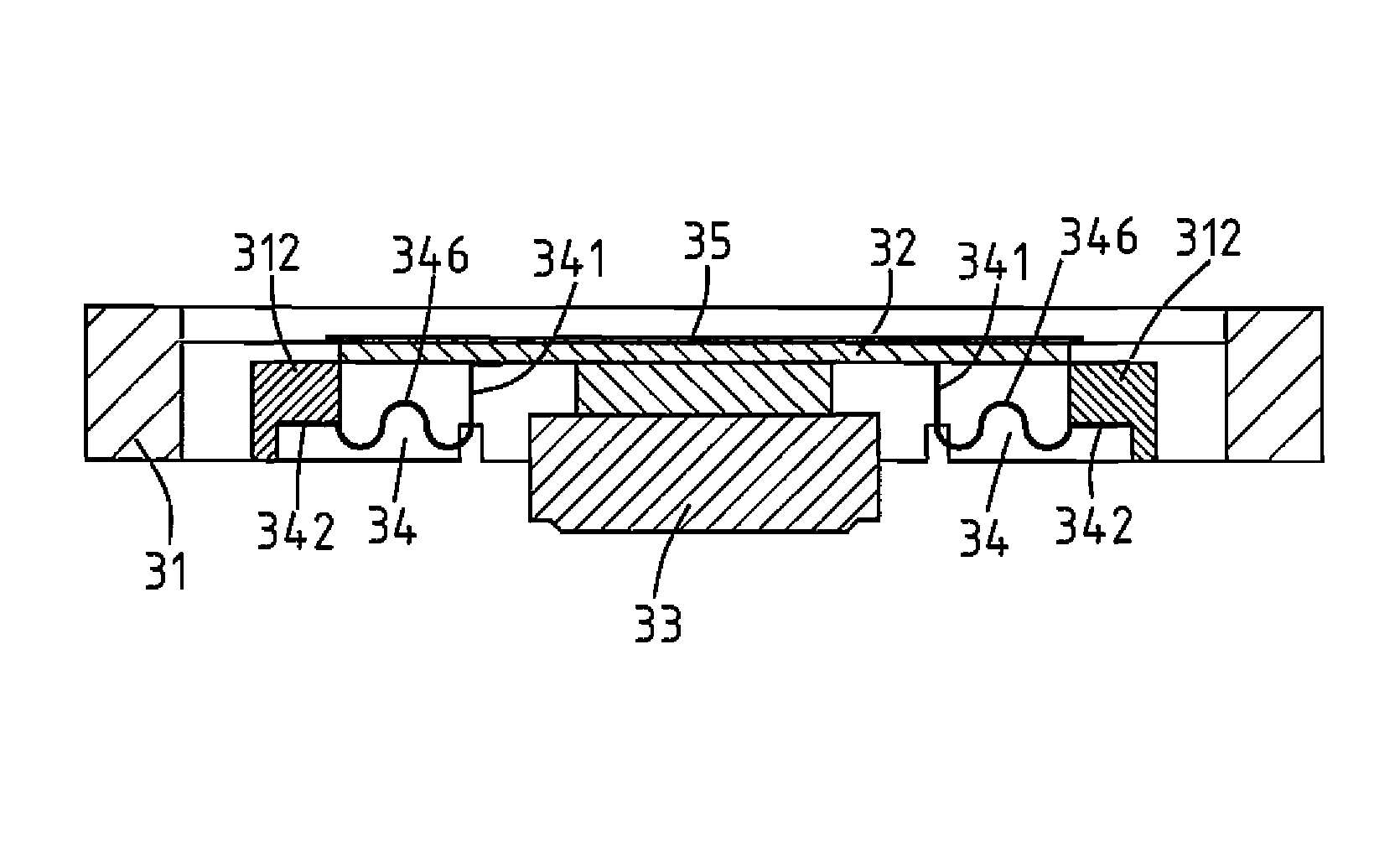
[0035]the present invention is shown in FIGS. 11 and 12. As illustrated, the planar speaker, similar to the previous embodiment, also contains a frame 31, a diaphragm 32, a driver 33, two suspension elements 34, and a surround 35. The frame 31 has a flat rectangular shape and the diaphragm 32 is suspended in a front opening of the frame 31 by the surround 35. The driver 33 is positioned in the center of the frame 31 behind the diaphragm 32. A voice coil of driver 33 is attached to a back surface of the diaphragm 32 so that a back-and-forth movement of the coil would cause the diaphragm 32 to vibrate and to produce sound waves.
[0036]Two beams 312 are arranged in parallel on either side of the driver 33 between two opposing longer side walls of the frame 31 and behind the diaphragm 32. The suspension elements 34 are made of a flexible material such as foam, rubber, plastic, or a composite material. Each suspension element 34 contains a vertical first arm segment 341, a lateral second ...
PUM
 Abstract
Description
Claims
Application Information
 - R&D
- Intellectual Property
- Life Sciences
- Materials
- Tech Scout
- Unparalleled Data Quality
- Higher Quality Content
- 60% Fewer Hallucinations
Browse by: Latest US Patents, China's latest patents, Technical Efficacy Thesaurus, Application Domain, Technology Topic, Popular Technical Reports.
© 2025 PatSnap. All rights reserved.Legal|Privacy policy|Modern Slavery Act Transparency Statement|Sitemap|About US| Contact US: help@patsnap.com


