
Inductive liquid-level sensor

a liquid level sensor and inductive technology, applied in liquid/fluent solid measurement, instruments, machines/engines, etc., can solve the problems of reducing the sensitivity of the sensor to manufacturing tolerances and calibration loss, and achieve the effect of reducing the sensitivity of the circuitry to manufacturing variations, reducing calibration loss, and ensuring accuracy

Active Publication Date: 2011-12-27
ILLINOIS TOOL WORKS INC
View PDF5 Cites 3 Cited by
  • Summary
  • Abstract
  • Description
  • Claims
  • Application Information

AI Technical Summary

Benefits of technology

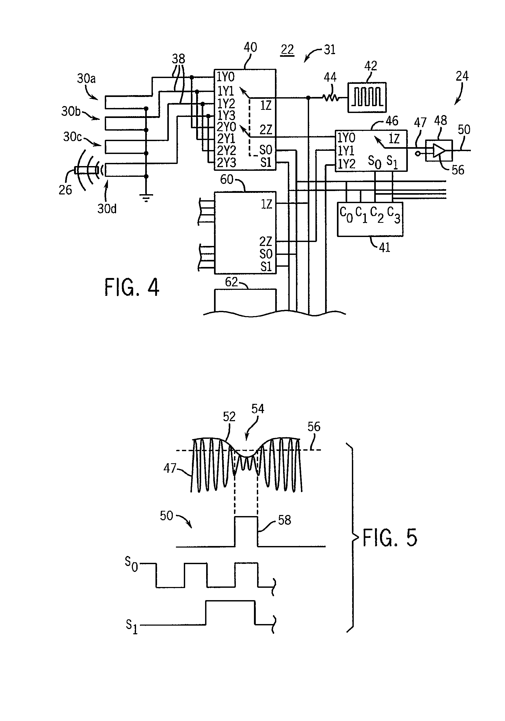
[0005]The present invention provides an inductive liquid height sensor employing a set of electrically independent loops each of which may separately sense the proximity of a metallic ring in a float. By interrogating the loops, the location of the float and thus the liquid height may be readily determined without the need for precise measurements of inductance. By reducing the inductance measurement to a simple threshold detection, the sensitivity of the circuitry to manufacturing variations and tuning drift is greatly reduced.
[0007]It is thus a feature of at least one embodiment of the invention to provide a robust liquid-height sensor. The use of inductive sensing allows a complete encapsulation of the electrical circuit for protection against possibly caustic liquids while the use of multiple independent loops greatly reduces sensitivity of the sensor to manufacturing tolerances and loss of calibration.
[0009]It is thus a feature of at least one embodiment of the invention to provide a simple method of fabricating the complex loop structure.
[0013]It is thus a feature of at least one embodiment of the invention to reduce cross coupling between the loops permitting closer loop spacing and / or greater sensitivity in the detection of the conductive element.
[0021]It is thus a feature of at least one embodiment of the invention to make use of inductive coupling to allow a slide fitting between the float and shaft permitting a simplified construction of the sensor where the float is guided by the shaft.

Problems solved by technology

The use of inductive sensing allows a complete encapsulation of the electrical circuit for protection against possibly caustic liquids while the use of multiple independent loops greatly reduces sensitivity of the sensor to manufacturing tolerances and loss of calibration.

Method used


Image

  • Inductive liquid-level sensor
  • Inductive liquid-level sensor
  • Inductive liquid-level sensor

Examples


Embodiment Construction

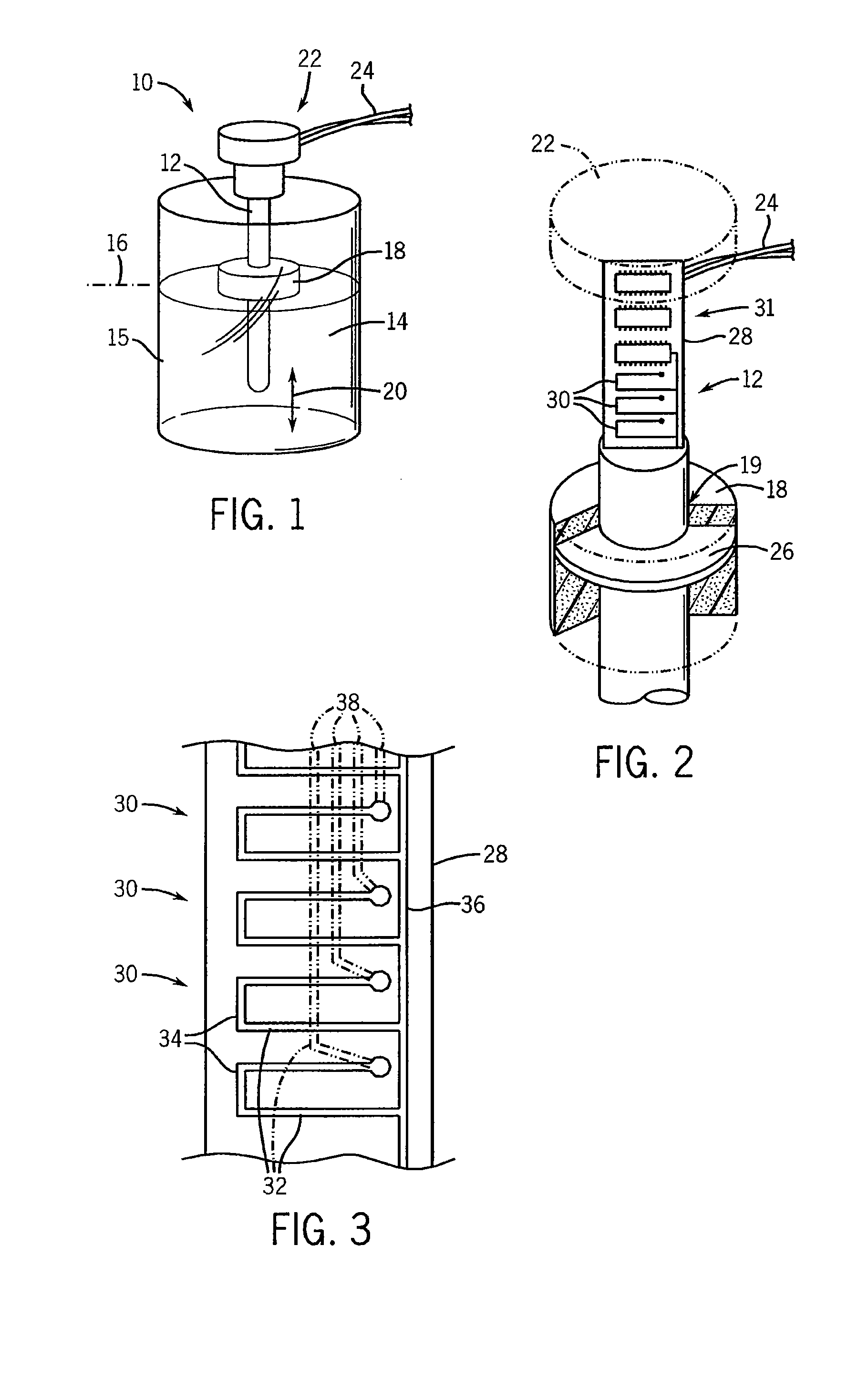
[0030]Referring now to FIG. 1, a sensor 10 according to the present invention may have a central cylindrical shaft 12 adapted to extend downward into a liquid 14 held in a tank 15, the liquid having a liquid height 16. The present invention contemplates that the liquid 14 may, for example, be a solution of urea forming part of an emission control system for diesel engines.

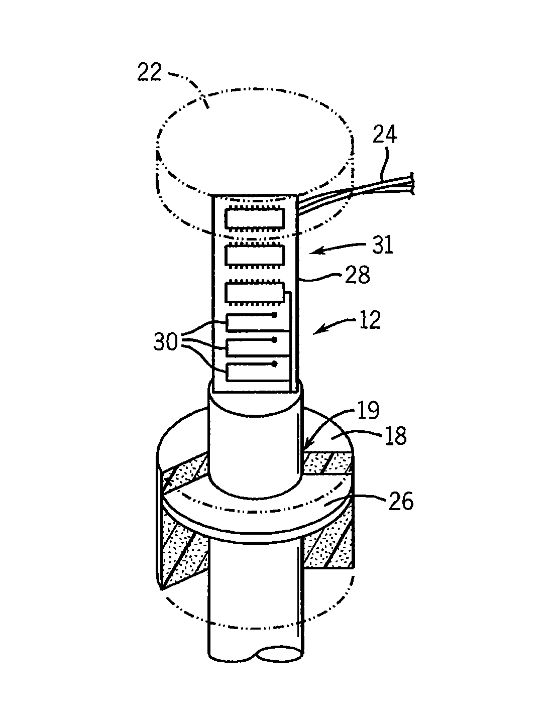
[0031]Referring also to FIG. 2, a float 18 having a central cylindrical bore 19 may fit about the cylindrical shaft 12 to slide freely in a vertical direction 20 (as depicted) to rise and fall with changes in the liquid height 16. The material of the float 18 may encapsulate a conductive material 26 embedded therein so that the conductive material 26 is shielded from the liquid 14, the conductive material 26 preferably being in the shape of a ring with the opening of the ring 26 being concentric with the bore 19. In this regard, the material of the float 18 may be, for example, a closed cell or encapsulated foam ma...


PUM


Abstract

An inductive liquid-level sensor employs a central shaft supporting multiple independent electrical loops that may be interrogated to detect the proximity of the conductive element in the float rising and falling with changes in liquid height outside of the shaft.

Description

CROSS REFERENCE TO RELATED APPLICATION[0001]This Non-Provisional Application claims benefit to U.S. Provisional Application Ser. No. 61 / 085,266 filed Jul. 31, 2008 hereby incorporated by reference.FIELD OF THE INVENTION[0002]The present invention relates to liquid-level sensors, particularly sensors that may be suitable for use in monitoring urea levels in diesel engine emission control systems such as those using “selective catalytic reduction” (SCR).[0003]A wide variety of liquid-level sensing technologies exist including those using ultrasonic signals, changes in capacitance, and changes in electrical resistance. One type of liquid-level sensor employs a loop, for example contained within a hollow shaft extending into the liquid. A float with a metal slug may slide up and down along the shaft with changes in the liquid height. The location of the metal slug along the length of the loop changes the inductance or mutual inductance of the loop which may be measured and converted int...

Claims


Application Information

Patent Timeline
Patent Type & Authority Patents(United States)
IPC IPC(8): G01F23/00G08B21/00
CPCG01F23/70
Inventor RUDD, JEFFREY P.
Owner ILLINOIS TOOL WORKS INC
Learn More