
Dual handle attachment for a single handle floor cleaning appliance and conversion method thereof

Inactive Publication Date: 2011-12-27
WILLEY JEANNE D
View PDF13 Cites 8 Cited by
  • Summary
  • Abstract
  • Description
  • Claims
  • Application Information

AI Technical Summary

Benefits of technology

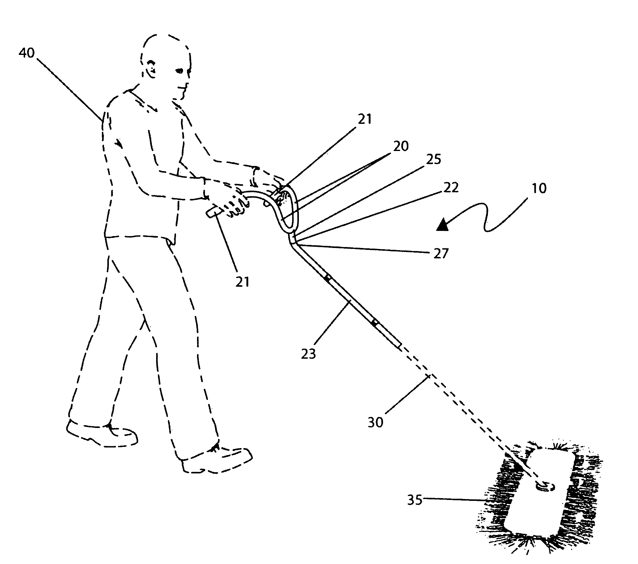
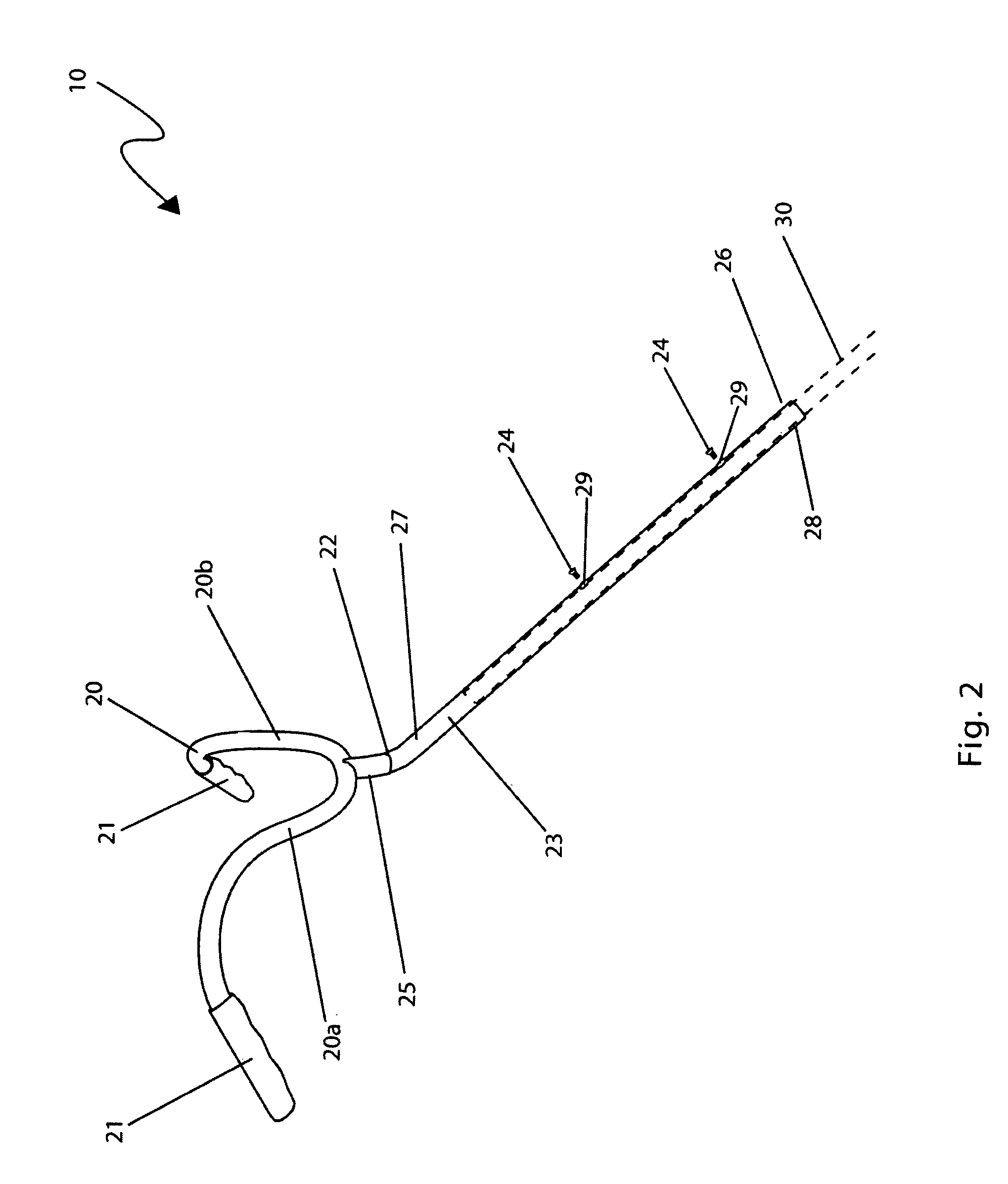
[0012]According to one aspect, the invention provides an auxiliary dual handle device for attachment to a handle of a floor cleaning appliance having a floor engaging portion. The device includes an elongated member which has a predetermined length and which is manufactured from a predetermined material. A bore is longitudinally and axially formed in at least a portion of the elongated member and which is sized and shaped to slidingly engage an exterior surface of the appliance handle. There is a left and a right auxiliary handle, each having a first end portion thereof rigidly secured to a user proximal end portion of the elongated member and laterally offset from one another. Means is provided for operably securing the elongated member to the appliance handle.
[0016]Another object of the present invention is to provide a dual handle device for floor cleaning appliances that relieves physical stress and strain to the user.
[0018]A further object of the present invention is to provide a dual handle device for floor cleaning appliances that is simple to install.

Problems solved by technology

While they undoubtedly do their job well, it does not mean they cannot be improved.
This is especially true for those who spend many hours pushing a mop with their hands, arms, and wrists at an uncomfortable angle to one another while twisting and potentially straining the upper body.
Additionally, the long handled nature of the mop makes it difficult to control, especially when trying to move the mop from side to side.

Method used


Image

  • Dual handle attachment for a single handle floor cleaning appliance and conversion method thereof
  • Dual handle attachment for a single handle floor cleaning appliance and conversion method thereof
  • Dual handle attachment for a single handle floor cleaning appliance and conversion method thereof

Examples


Embodiment Construction

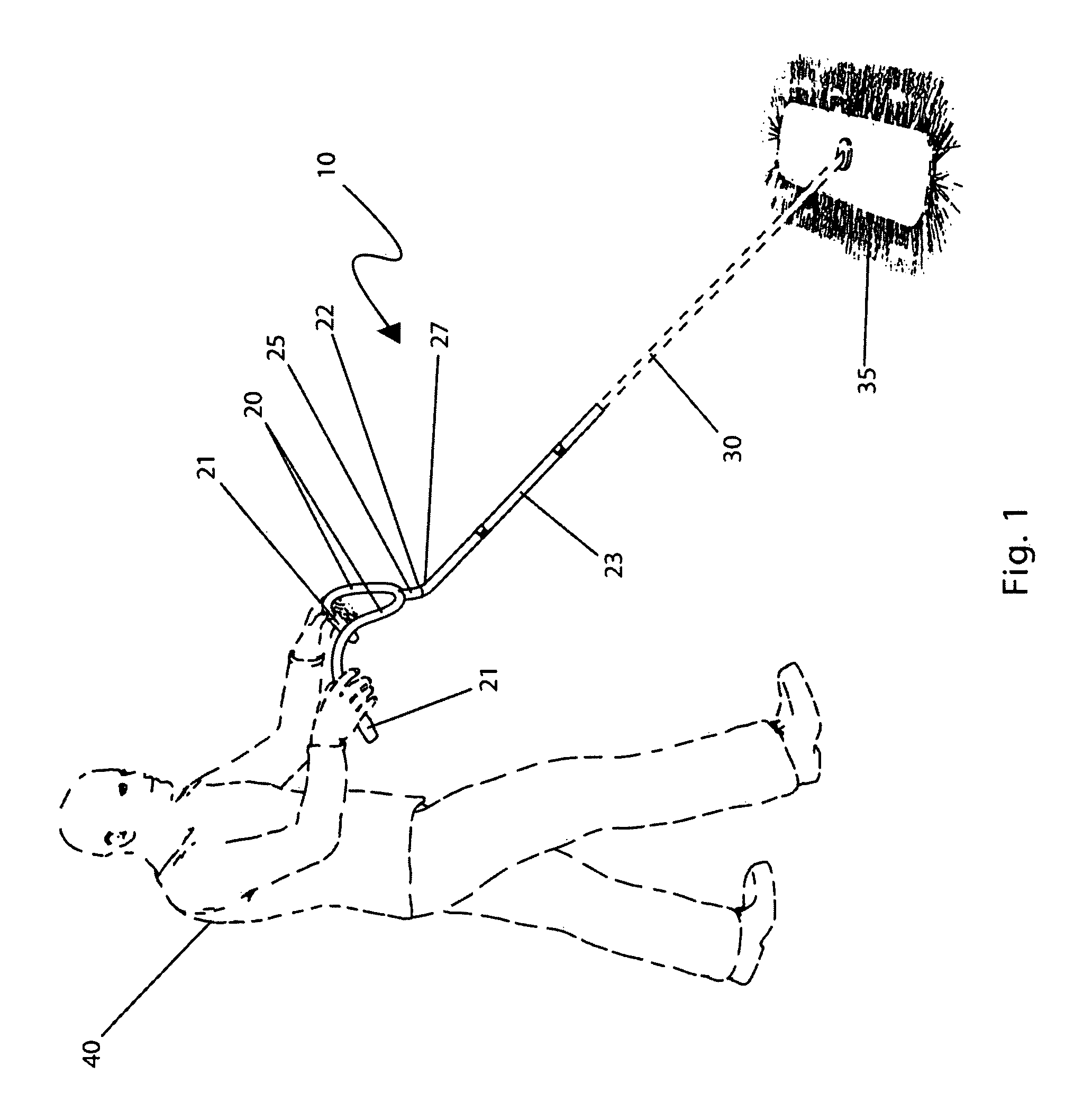
[0028]The best mode for carrying out the invention is presented in terms of its preferred embodiment, herein depicted within FIGS. 1 and 2. However, the invention is not limited to the described embodiment and a person skilled in the art will appreciate that many other embodiments of the invention are possible without deviating from the basic concept of the invention, and that any such work around will also fall under scope of this invention. It is envisioned that other styles and configurations of the present invention can be easily incorporated into the teachings of the present invention, and only one particular configuration shall be shown and described for purposes of clarity and disclosure and not by way of limitation of scope.

[0029]The terms “a” and “an” herein do not denote a limitation of quantity, but rather denote the presence of at least one of the referenced items.

[0030]It is to be understood that the definition of a floor cleaning appliance includes but is not limited t...


PUM


Abstract

An auxiliary dual handle device for attachment to a handle of a floor cleaning appliance having a floor, engaging portion includes an elongated member which has a predetermined length and which is manufactured from a predetermined material and a bore which is longitudinally and axially formed in at least a portion of the elongated member and which is sized and shaped to slidingly engage an exterior surface of the appliance handle. There is a left and a right auxiliary handle, each having a first end portion thereof rigidly secured to a user proximal end portion of the elongated member and laterally offset from one another. The elongated member is secured to the appliance handle with fasteners of clamps. There is also provided a single piece dual handle device which is attachable directly to the floor engaging portion of the floor cleaning appliance.

Description

RELATED APPLICATIONS[0001]The present invention was first described in and claims the benefit of Disclosure Document No. 609,152 filed on Nov. 16, 2006.FIELD OF THE INVENTION[0002]The present invention relates, in general, to handles for various devices and, more particularly, this invention relates to an ergonomic dual handle device for various floor cleaning appliances to relieve physical stress and strain to the user while improving manual control of the floor cleaning appliances and, yet more particularly, the instant invention relates to converting a single elongated handle of a floor cleaning appliance into an ergonomically disposed dual handle arrangement.BACKGROUND OF THE INVENTION[0003]Floor cleaning appliance having a floor engaging cleaning head and an elongated handle extending therefrom are well known in the art. Perhaps one of the most common long-handled floor cleaning devices seen on a daily basis is that of industrial push style dust mop. They have been used for gen...

Claims


Application Information

Patent Timeline
IPC IPC(8): A46B5/02
CPCA46B5/02A47L13/20B25G1/04B25G3/20Y10T16/476A46B2200/302
Inventor WILLEY, JEANNE D.
Owner WILLEY JEANNE D
Learn More