
Projection of subsurface structure onto an object's surface

a subsurface structure and object technology, applied in the field of diffuse infrared light generation, can solve the problems of difficulty lack of performance of previous imaging systems designed to aid in finding such blood vessels, and achieve the effect of improving the visibility of subcutaneous blood vessels

Inactive Publication Date: 2011-12-13
CHRISTIE MEDICAL HLDG
View PDF76 Cites 84 Cited by
  • Summary
  • Abstract
  • Description
  • Claims
  • Application Information

AI Technical Summary

Benefits of technology

The system significantly improves the visibility of subcutaneous blood vessels by providing high contrast and reducing interference, allowing for accurate localization without discomfort to the patient.

Problems solved by technology

This can be a difficult task, especially when the blood vessel is small and / or the vessel is under a significant deposit of subcutaneous fat or other tissue.
The performance of previous imaging systems designed to aid in finding such blood vessels has been lacking.

Method used


Image

  • Projection of subsurface structure onto an object's surface
  • Projection of subsurface structure onto an object's surface
  • Projection of subsurface structure onto an object's surface

Examples


Embodiment Construction

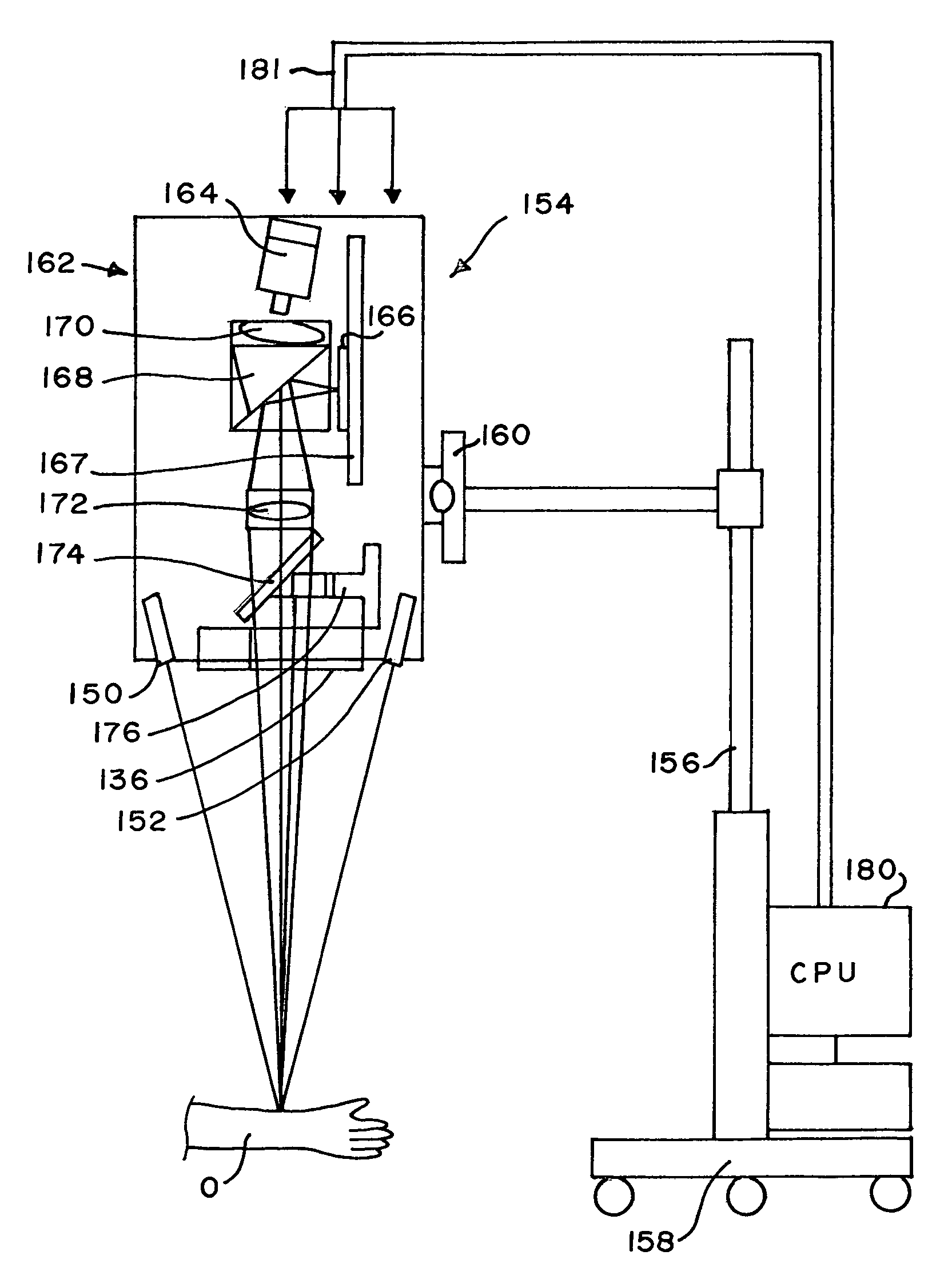
[0044]Skin and some other body tissues reflect infrared light in the near-infrared range of about 700 to 900 nanometers, while blood absorbs radiation in this range. Thus, in video images of body tissue taken under infrared illumination, blood vessels appear as dark lines against a lighter background of surrounding flesh. However, due to the reflective nature of subcutaneous fat, blood vessels that are disposed below significant deposits of such fat can be difficult or impossible to see when illuminated by direct light, that is, light that arrives generally from a single direction.

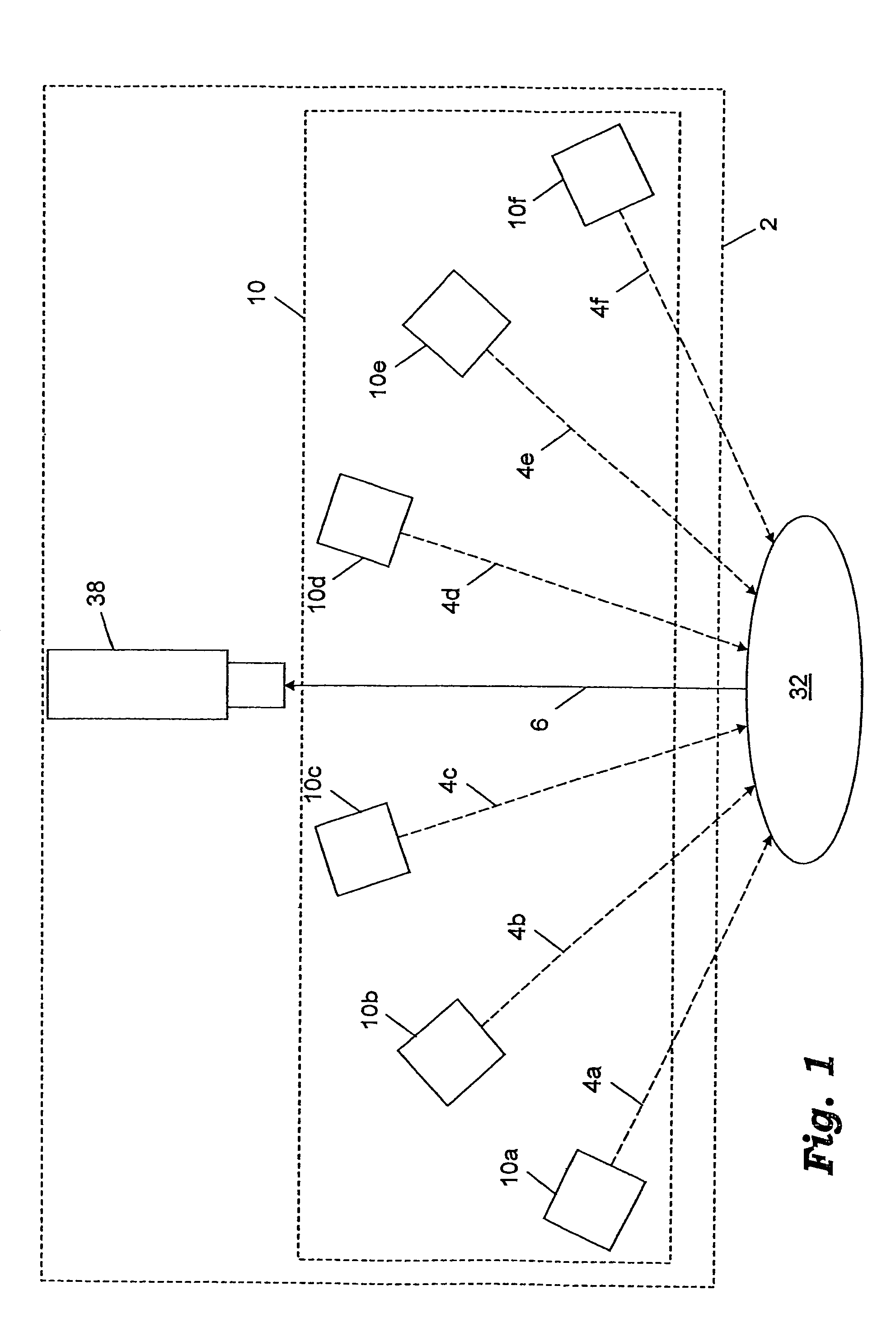
[0045]The inventor has determined that when an area of body tissue having a significant deposit of subcutaneous fat is imaged in near-infrared range under illumination of highly diffuse infrared light, there is significantly higher contrast between the blood vessels and surrounding flesh than when the tissue is viewed under direct infrared illumination. Although the invention should not be limited by any p...


PUM

PropertyMeasurementUnit
wavelengthsaaaaaaaaaa
total lengthaaaaaaaaaa
widthaaaaaaaaaa

Abstract

An imaging system illuminates an object with infrared light to enhance visibility of buried structure beneath the surface of the object, and projects a visible light image of the buried structure onto the surface of the object. The system may include an infrared light source for generating the infrared light and a structure for diffusing the infrared light. The diffusing structure may include one or more layers of diffusing material for diffusing the light. The system further includes a video imaging device for receiving the infrared light reflected from the object and for generating a video image of the buried structure based on the reflected infrared light. The buried structure may be a subcutaneous blood vessel. A calibration procedure is described as well as embodiments for ensuring that the object is maintained in focus at the correct distance.

Description

CROSS REFERENCE TO RELATED APPLICATIONS[0001]This application is a continuation-in-part, and claims priority benefit, of U.S. patent application Ser. No. 10 / 386,249 (filed Mar. 11, 2003) entitled Imaging System using Diffuse Infrared Light (hereby specifically incorporated by reference in its entirety), which issued as U.S. Pat. No. 7,239,909 on Jul. 3, 2007, which itself was a continuation-in-part, and claims priority benefit, of U.S. patent application Ser. No. 09 / 487,007 (filed Jan. 19, 2000) entitled Diffuse Infrared Light Imaging System, which issued as U.S. Pat. No. 6,556,858 on Apr. 29, 2003 (hereby specifically incorporated by reference in its entirety).STATEMENT REGARDING FEDERALLY SPONSORED RESEARCH OR DEVELOPMENT[0002]Not applicable.REFERENCE TO COMPACT DISC(S)[0003]Not applicable.TECHNICAL FIELD[0004]The present invention is generally directed to generation of diffuse infrared light. More particularly, the invention is directed to a system for illuminating an object with...

Claims


Application Information

Patent Timeline
Patent Type & Authority Patents(United States)
IPC IPC(8): A61B6/00G01N21/27A61B5/00A61B5/107G01N21/35H04N5/235H04N5/33
CPCA61B5/0059A61B5/489H04N5/2354H04N5/33A61B5/0086H04N23/74H04N23/20A61B2090/366A61B90/36
Inventor ZEMAN, HERBERT D.LOVHOIDEN, GUNNARVRANCKEN, CARLOSSNODGRASS, JOHNDELONG, JAMES A.
Owner CHRISTIE MEDICAL HLDG
Learn More