
Shift control device for automatic transmission and control method thereof

a technology of automatic transmission and control device, which is applied in the direction of electric devices, machines/engines, instruments, etc., can solve the problems of deteriorating driving ability, and achieve the effect of preventing drivability from deteriorating and improving shift toleran

Active Publication Date: 2011-11-22
JATCO LTD +1
View PDF15 Cites 4 Cited by
  • Summary
  • Abstract
  • Description
  • Claims
  • Application Information

AI Technical Summary

Benefits of technology

[0009]It is an object of this invention to prevent drivability from deteriorating by improving shift tolerance.

Problems solved by technology

However, in the conventional technique described above, only time is used as a parameter, regardless of the type of shift and input torque, and the type of the next shift is not taken into account.
Therefore, even when a determined shift would not generate a large amount of heat and the frictional element would not reach the damage temperature if the shift was performed, the shift is prohibited, and as a result, drivability deteriorates.

Method used


Image

  • Shift control device for automatic transmission and control method thereof
  • Shift control device for automatic transmission and control method thereof
  • Shift control device for automatic transmission and control method thereof

Examples


Embodiment Construction

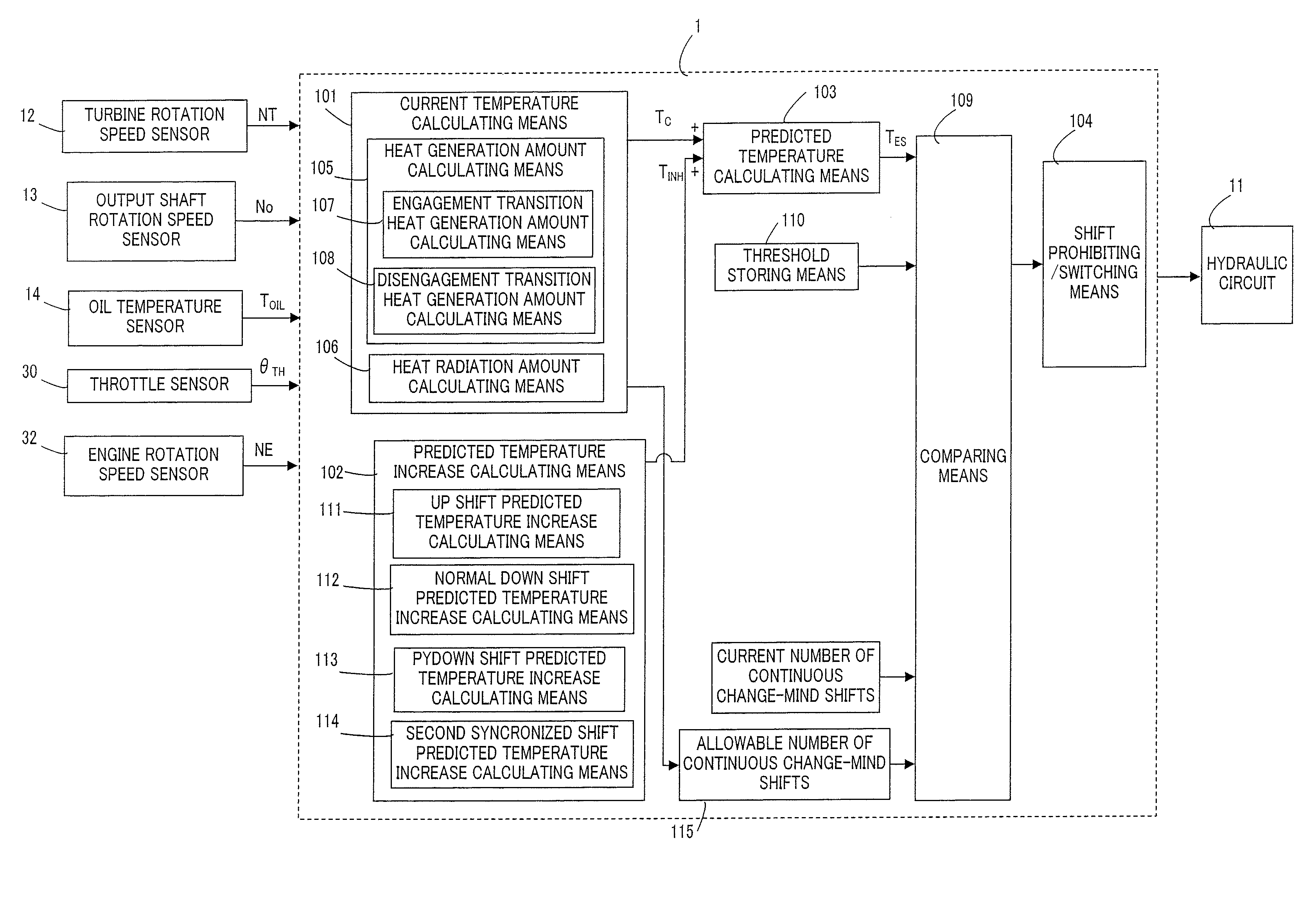
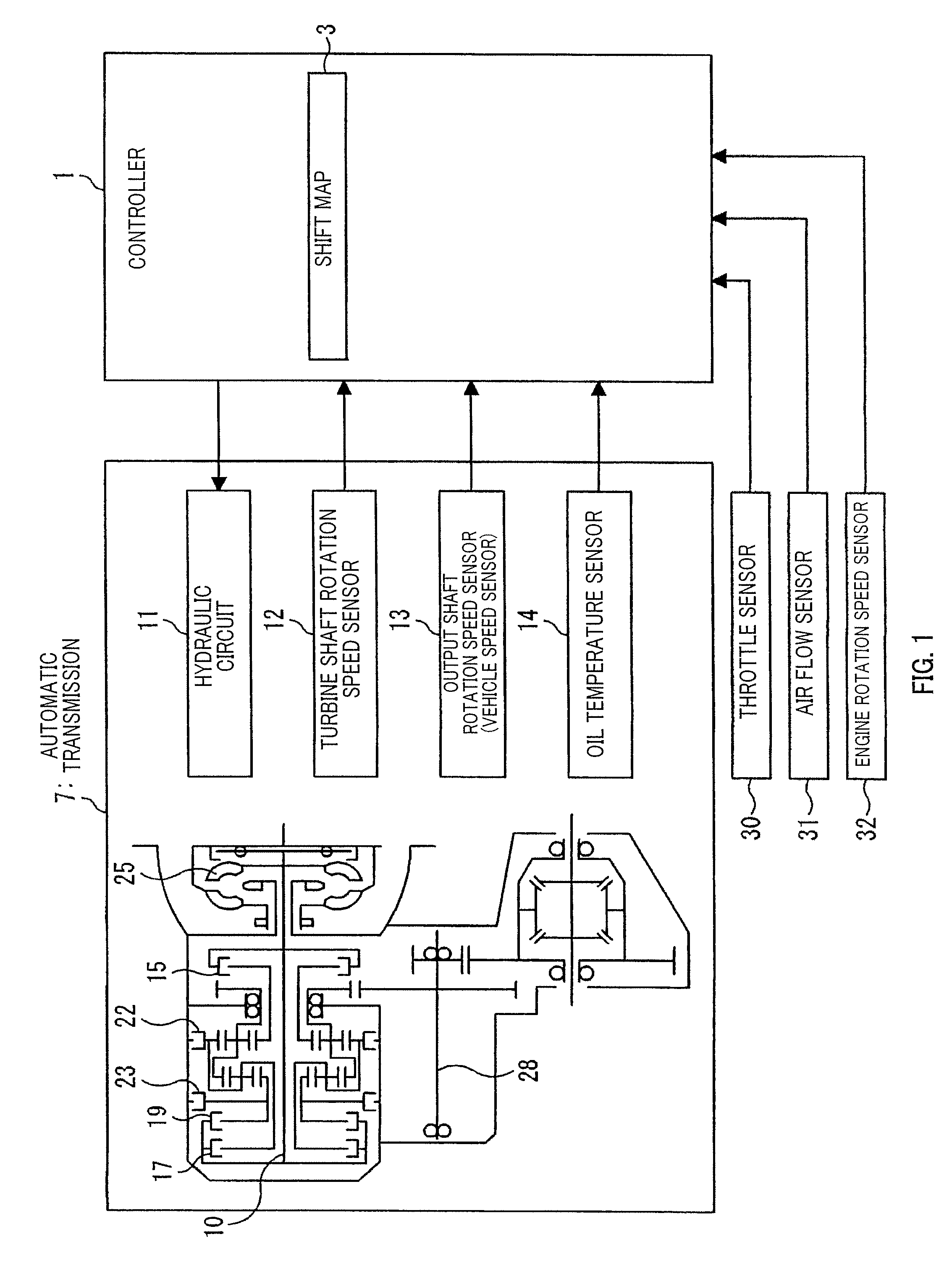
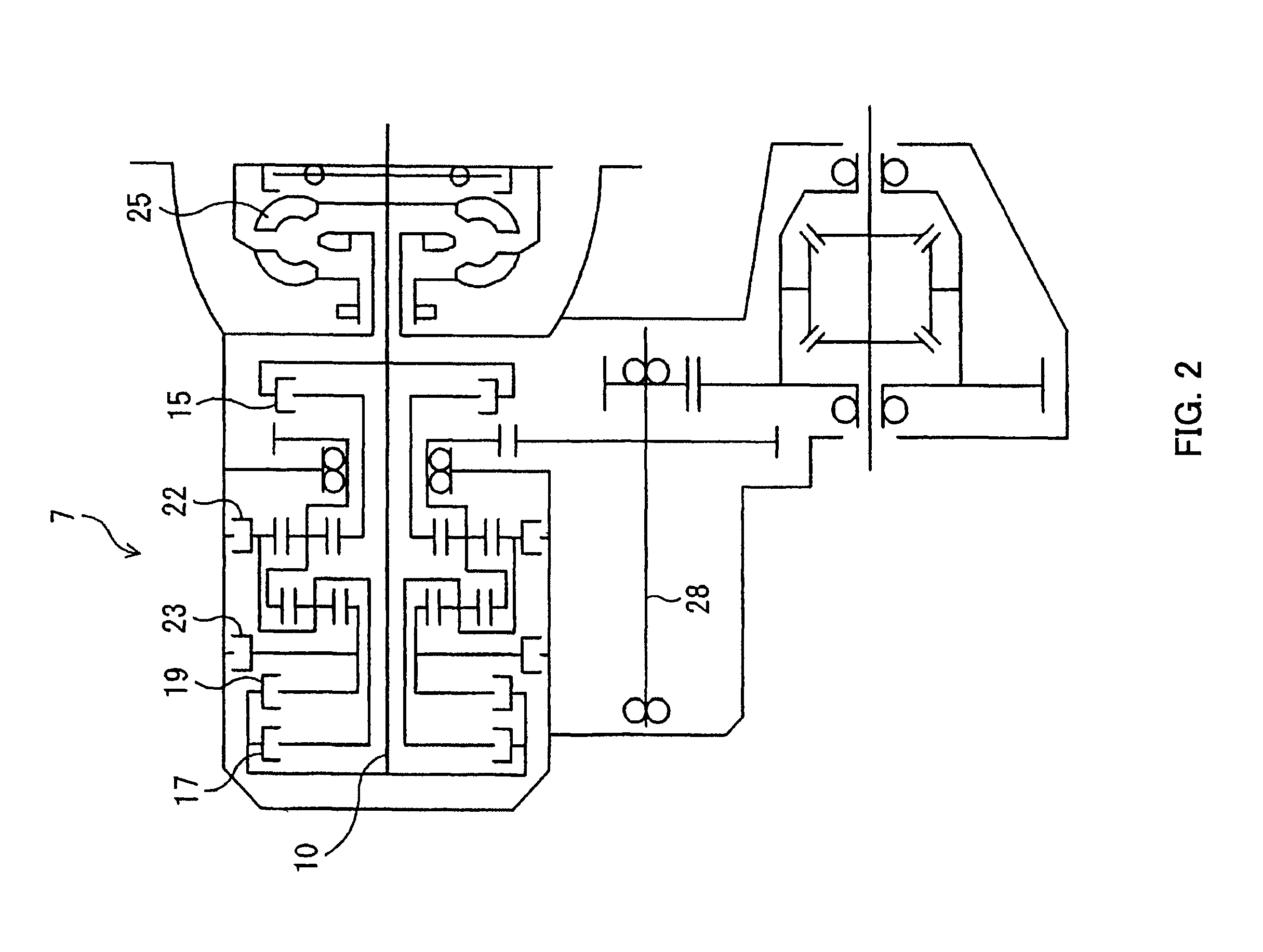
[0034]An embodiment of this invention will be described in detail below with reference to the figures and so on. FIG. 1 is a functional block diagram showing the constitution of a shift control device for an automatic transmission according to this embodiment. FIG. 2 is a skeleton diagram showing the constitution of the automatic transmission. As shown in FIG. 1, the shift control device comprises a controller 1, various sensors including an input shaft rotation speed sensor (turbine shaft rotation speed sensor) 12 that detects a rotation speed NT of a turbine 25 and a turbine shaft 10, an output shaft rotation speed sensor (vehicle speed sensor) 13 that detects a rotation speed No of an output shaft 28, an oil temperature sensor 14 that detects a temperature of ATF (automatic transmission oil), a throttle sensor 30 that detects a throttle opening of an engine, not shown in the figures, an air flow sensor 31 that detects an intake air amount of the engine, and an engine rotation spe...


PUM


Abstract

An automatic transmission calculates a current thermal load state of the frictional element, predicts (S24, 531), prior to the start of the shift, a heat generation amount of the frictional element during the shift, predicts (S25, S32) a thermal load state of the frictional element upon shift completion on the basis of the current thermal load state and the predicted heat generation amount, and when the predicted thermal load state upon shift completion is inside a predetermined region, either performs (S28, S38) the shift after modifying a shift mode such that the heat generation amount of the frictional element is smaller than that of a case in which the predicted thermal load state upon shift completion is outside the predetermined region, or prohibits (S39) the shift, wherein the predetermined region is set at a different region depending on whether the shift is an upshift or a downshift.

Description

FIELD OF THE INVENTION[0001]This invention relates to a shift control device for an automatic transmission.BACKGROUND OF THE INVENTION[0002]In a typical conventional automatic transmission for an automobile, the rotation of an engine is input via a torque converter, varied in speed by a shift mechanism having a plurality of planetary gears, and output to a drive shaft or a propeller shaft (the axle side).[0003]The shift mechanism of this type of automatic transmission executes a shift by transmitting the rotation of an input shaft to a specific gear or carrier of the planetary gear in accordance with a shift position and transmitting the rotation of the specific gear or carrier to an output shaft appropriately. The shift mechanism also comprises a plurality of frictional elements such as clutches and brakes to converge the rotation of the specific gear or carrier appropriately during the shift, and performs a predetermined shift by switching a torque transmission path in accordance ...

Claims


Application Information

Patent Timeline
Patent Type & Authority Patents(United States)
IPC IPC(8): G06F7/00
CPCF16H59/72F16H61/0213B60W30/186F16H61/16F16H2059/725Y10T477/69387Y10T477/60Y10T477/69373Y10T477/653Y10T477/619F16H2061/0241
Inventor IKEDA, TOMOMASAKAWAKAMI, HIROKI
Owner JATCO LTD
Learn More