Child stroller
a technology for strollers and children, applied in the field of strollers, can solve problems such as serious interference between poles, and achieve the effect of little interference between components
- Summary
- Abstract
- Description
- Claims
- Application Information
AI Technical Summary
Benefits of technology
Problems solved by technology
Method used
Image
Examples
first embodiment
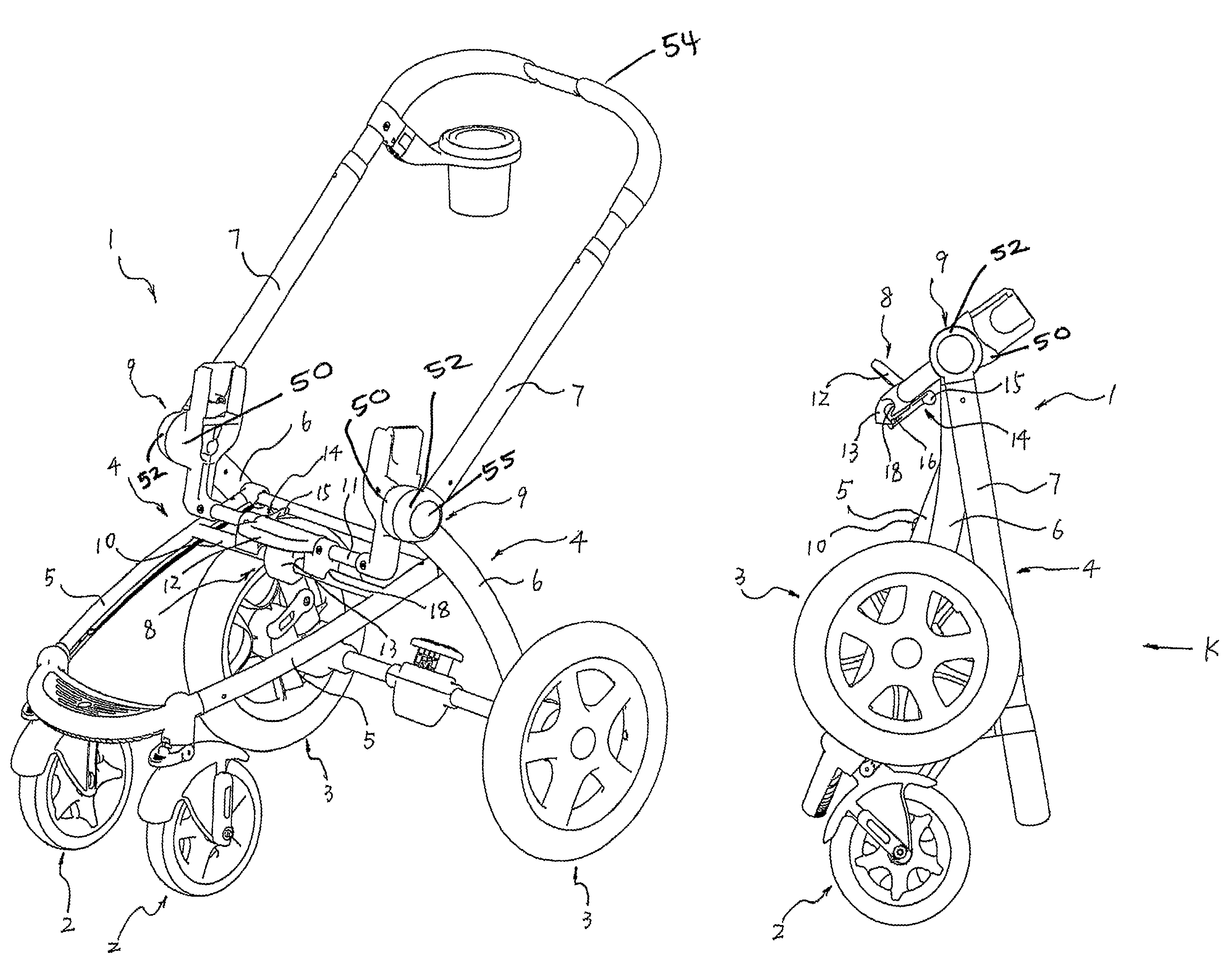
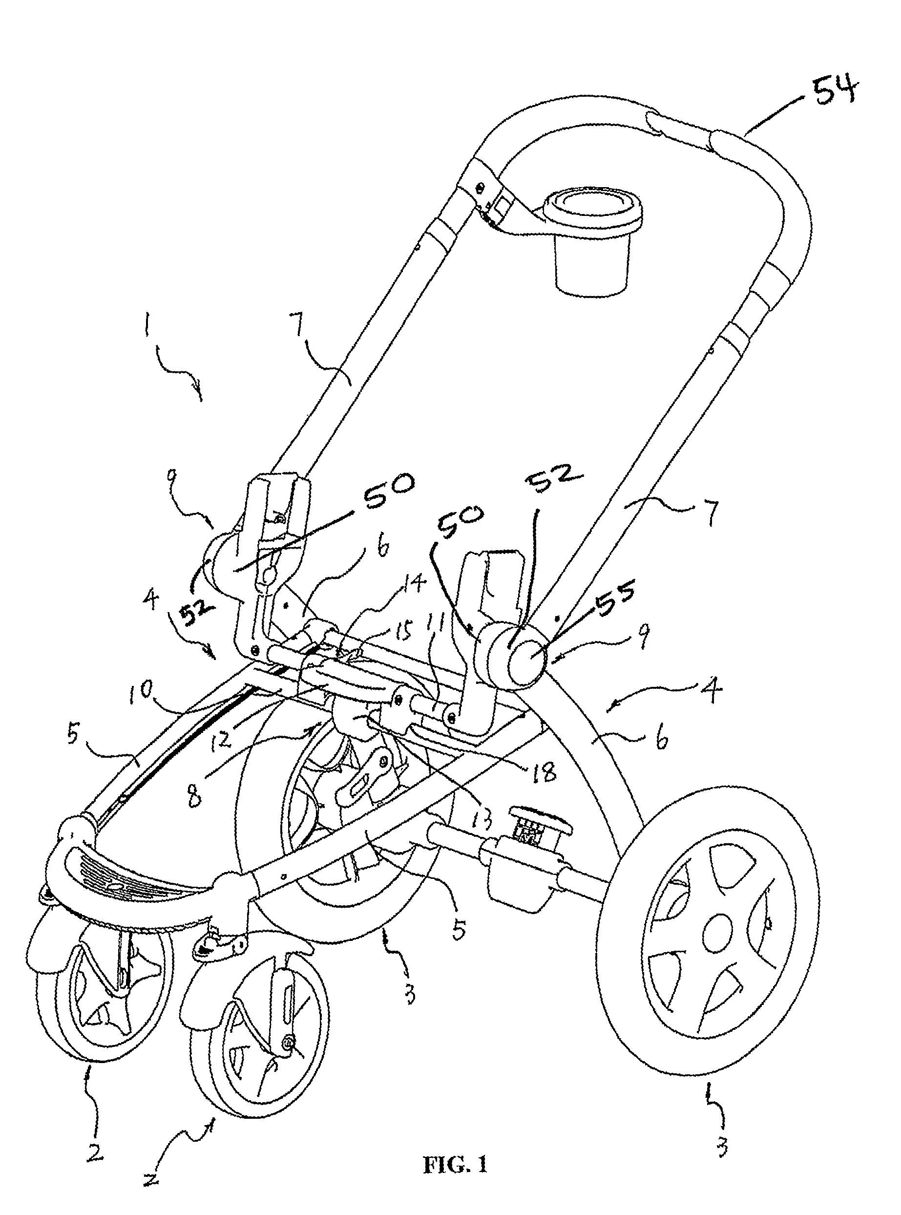
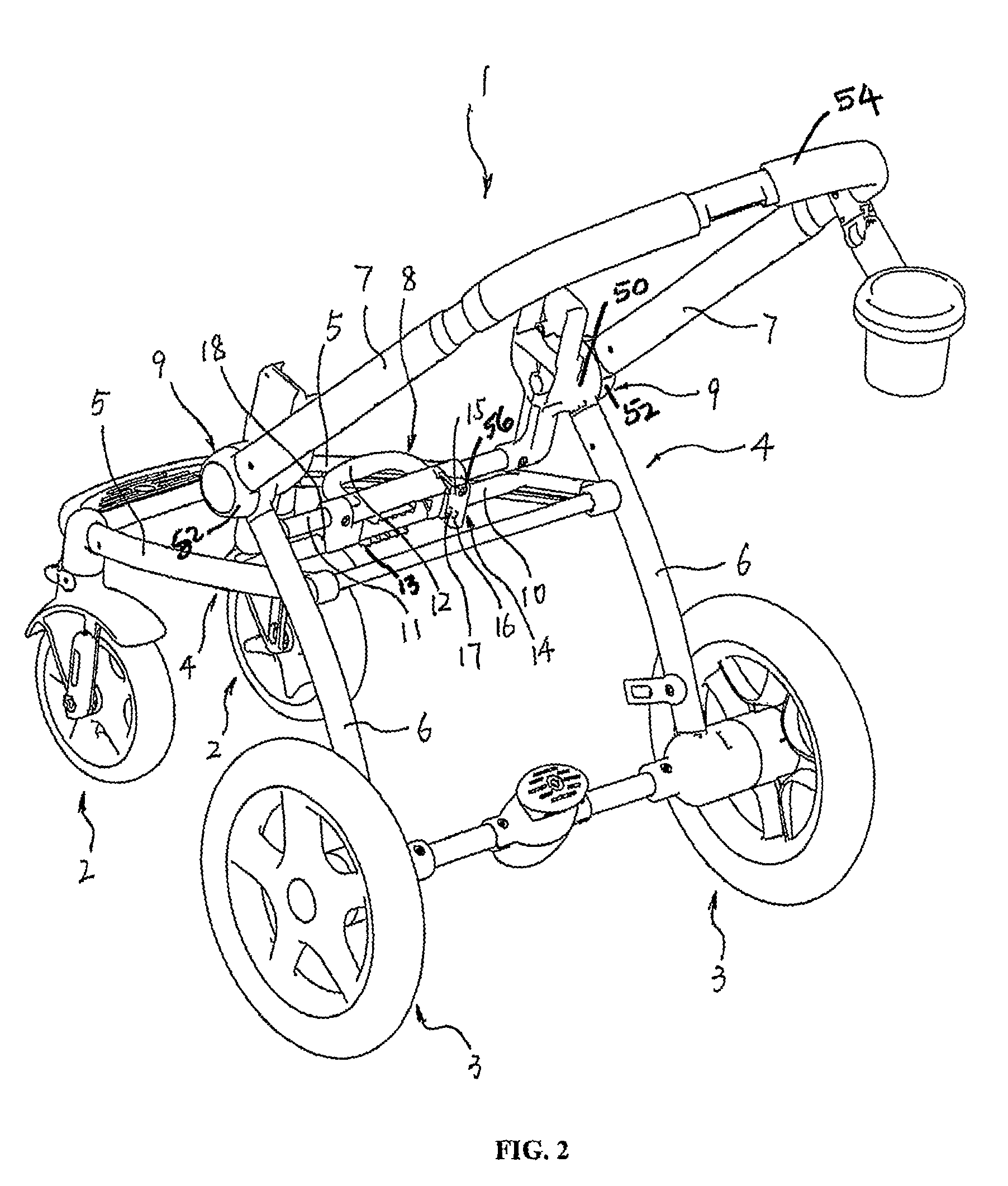
[0038]With reference to FIG. 1 through FIG. 8, the child stroller comprises a foldable stroller frame 1, a pair of front wheels or front wheel groups 2 mounted under a forward portion of the stroller frame 1, and a pair of rear wheels or rear wheel groups 3 mounted under a rear portion of the stroller frame 1. The stroller frame 1 includes two side frames 4 bilaterally set and a plurality of crossbars extending transversely between the two side frames 4. Each side frame 4 comprises a front leg 5 for mounting a respective front wheel 2, a rear leg 6 for mounting a respective rear wheel 3, the rear leg 6 being rotatably connected with the rear end of a rearwardly extending portion of the front leg 5, a handle member or handspike 7 with the lower end connected to the upper end of the rear leg 6, and a positioning device 9 set at the joint of the handspike 7 and the rear leg 6. The positioning device 9 has a locking state, in which the handspike 7 and the rear leg 6 are immovably conne...
second embodiment
[0050]With reference to FIG. 9, FIG. 10 and FIG. 12, the child stroller comprises a foldable stroller frame 1, two front wheel groups 2 mounted under the foreside of the stroller frame 1, two rear wheel groups 3 mounted under the rearward of the stroller frame 1, the stroller frame 1 including two side frames 4 bilaterally set and a plurality of crossbars set between the two side frames 4. Each side frame 4 comprises a front leg 5 for mounting the front wheel group 2, a rear leg 6 for mounting the rear wheel group 3, the upside of the rear leg 6 being rotatably connected with the rear end of the front leg 5, and a handspike 7 with the lower end connected to the upper end of the rear leg 6. A positioning device 9 is set at the joint of the handspike 7 and the rear leg 6, the positioning device 9 having a locking state, in which the handspike 7 and the rear leg 6 are immovably connected, and an unlocking state, in which the handspike 7 and the rear leg 6 are rotateably connected. A s...
PUM
 Abstract
Description
Claims
Application Information
 - R&D
- Intellectual Property
- Life Sciences
- Materials
- Tech Scout
- Unparalleled Data Quality
- Higher Quality Content
- 60% Fewer Hallucinations
Browse by: Latest US Patents, China's latest patents, Technical Efficacy Thesaurus, Application Domain, Technology Topic, Popular Technical Reports.
© 2025 PatSnap. All rights reserved.Legal|Privacy policy|Modern Slavery Act Transparency Statement|Sitemap|About US| Contact US: help@patsnap.com


