Tangential combustion turbine

a technology of tangential combustion turbine and combustion turbine, which is applied in the direction of gas turbine plants, rotary or oscillating piston engines, rotary piston engines, etc., can solve the problems of heavy oscillating and rotating parts, unsatisfactory modern requirements for more economic, environmental friendly and higher performance engines, and high vibration

Inactive Publication Date: 2011-11-22
ZINK ALEXANDER M +2
View PDF11 Cites 15 Cited by
  • Summary
  • Abstract
  • Description
  • Claims
  • Application Information

AI Technical Summary

Problems solved by technology

The classical Otto, Diesel, and Wankel engines, with the first two having a development history of more than 100 years, have meanwhile reached very high performances, but are still less than ideal regarding the modern requirements for more economic, environmental friendlier as well as for higher performance engines.
Some of the main disadvantages of these engines are the occurring of the ignition only after two or four revolutions, high vibrations, two dead rotation points in the power transmission from piston to the crank shaft, many heavy oscillating and rotating parts to be balanced etc.
The vibrations and sealing problems of the Wankel engine have not been solved yet.
Most of the rotational engines are based on the Wankel design, or have pulsating piston systems within circular trajectories and need complicated gears for the conversion of the chemical energy into mechanical power, and thus deliver low efficiency.
Some of these engines with more tangential action of the ignition do have large pendulant components and shapes that are difficult to seal.
These engines provide a reduced number of ignitions per rotation and have relatively low compression rates, what makes them economically obsolete.
The well known Gas Turbines are ideal for the airplane industry, especially for high speed and high performances, but are not economical for slower and smaller means of transportation.
There are always reliability issues with the rotary vanes in a rotating engine.
The structure to house the vanes and allow them to move becomes complicated and requires a robust setup to allow reliable, consistent operation.
The reliability of the gas sealing and the movement of the vanes is always questionable.
The seal between the inner rotor and outer rotor is always a complicated matter due to the geometry match of the rotating member to the stationary casing.
This type of engine has not been widely implemented due to problems of sealing within combustion chamber, poor durability, low fuel efficiency at low loads, and undesirable emissions.

Method used


Image

  • Tangential combustion turbine
  • Tangential combustion turbine
  • Tangential combustion turbine

Examples


Embodiment Construction

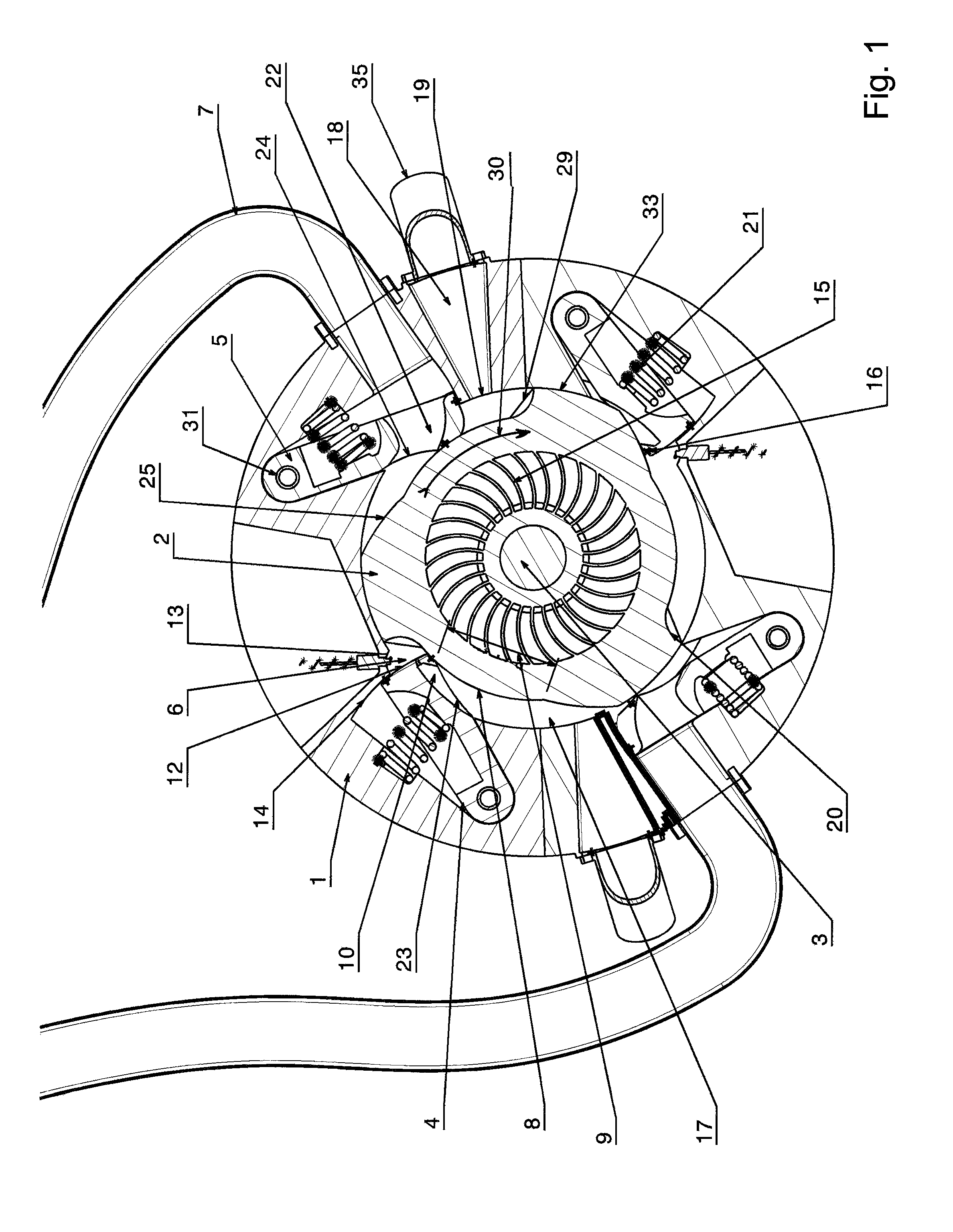
[0019]The present invention permits the construction of very compact engines with less moving parts, and the components are relatively simple and easy to manufacture. The present invention is a Tangential Combustion Turbine, and may also be called the Zink's Engine, and offers the advantage of a cleaner and more controllable combustion which results in better efficiency compared to the classical engines. This favors the use of this Tangential Combustion Turbine for the auto and airplane industry, as well as the generation of electrical power.

[0020]The present invention creates an engine which combines the principle of the internal combustion engines of Otto and Diesel (based on the Carnot Cycle) with the function and efficiency of the jet engines (based on the Brayton Cycle) in order to employ the combination of their best parameters. The present invention implements a hybrid Carnot-Brayton cycle in an intermittent manner and at much lower RPM rates compared with the gas turbines. F...


PUM


Abstract

A tangential combustion turbine is disclosed which is based on a casing, a rotor, and moving levers. A radial compressor is attached to the rotor and creates air pressure which pushes air into the combustion chamber based on the position and design of the combustion lever. The combustion chamber is defined by spaces between rotor lobes, and by combustion levers and exhaust levers which follow the rotor surface. A premix fuel system or direct fuel injection is used to create combustion. The exhaust gases then pass through the exhaust lever into the exhaust piping as the rotor rotates.

Description

CROSS REFERENCE TO RELATED APPLICATIONS[0001]This application claims the benefit of German Application No. DE 10 2008 050 014.3 filed on Nov. 1, 2008, now German Patent No DE 10 2008 050 014, which claims the benefit of German Application No. DE 10 2008 019 262.7, filed on Apr. 17, 2008, now abandoned.STATEMENT REGARDING FEDERALLY SPONSORED RESEARCH OR DEVELOPMENT[0002]Not applicable.REFERENCE TO SEQUENCE LISTING, A TABLE, OR COMPUTER PROGRAM LISTING[0003]Not applicable.BACKGROUND OF THE INVENTION[0004](1) Field of the Invention[0005]This application is directed to a rotational combustion turbine or engine, with a stationary casing and a rotating part, in which the thermodynamic expansion power released during the burning of an oxygen / combustible mixture of fuel within defined chambers, works directly against a rotor, and is directly transformed into mechanical power.[0006](2) Description of Related Art[0007]The classical Otto, Diesel, and Wankel engines, with the first two having a...

Claims


Application Information

Patent Timeline
Patent Type & Authority Patents(United States)
IPC IPC(8): F02B53/00
CPCF01C1/46F01C11/006F02C3/16
Inventor ZINK, ALEXANDER M.ZINK, ALEXANDER S.ZINK, MICHAEL M.
Owner ZINK ALEXANDER M
Why Eureka
Try Eureka