Eureka AIR delivers breakthrough ideas for toughest innovation challenges, trusted by R&D personnel around the world.

Paper supply mechanism and roll paper printer

a paper supply mechanism and printer technology, applied in the direction of printers, instruments, transportation and packaging, etc., can solve the problems of reducing paper transportation precision, side walls pushing forcefully against the ends of the roll paper, and excessive paper transportation load

Active Publication Date: 2011-11-01
SEIKO EPSON CORP
View PDF15 Cites 9 Cited by
  • Summary
  • Abstract
  • Description
  • Claims
  • Application Information

AI Technical Summary

Benefits of technology

[0020]Furthermore, because the edge of the roll paper can be aligned to one side wall, problems caused by the roll paper shifting sideways or the paper meandering or becoming skewed when the roll paper is conveyed can be prevented.
[0027]However, because the roller body in this aspect of the invention can slide widthwise relative to the roll paper compartment, the roller body slides together with the roll paper when the roll paper is moved widthwise to the roll paper compartment. The roll paper can therefore be easily moved widthwise to the roll paper compartment.
[0029]Another aspect of at least one embodiment of the invention is a roll paper printer having the roll paper supply mechanism described above. This avoids problems caused by an increased paper transportation load as well as meandering and skewing of the printing position when roll paper of a different paper width is loaded. Furthermore, because the printing position can be conveyed more accurately, a drop in print quality caused by deficient roll paper transportation in the roll paper printer can also be prevented.
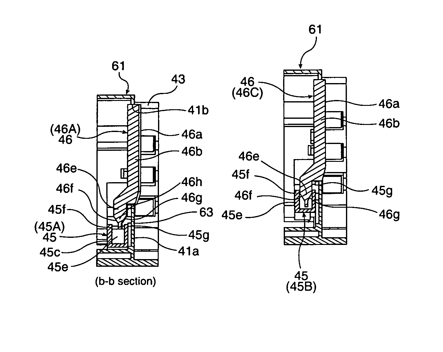
[0030]When the first side wall of a roll paper supply mechanism according to the at least one embodiment of invention is moved in the storage width direction in order to adjust the paper storage width of the roll paper compartment, a roll paper urging member disposed to the first side wall is held in a position between a protruding position and a retracted position. The first side wall and second side wall can therefore be positioned substantially at the width of the paper with the roll paper held therebetween. This position leaves a margin of movement (a range of movement) in the roll paper urging member in the protruding direction and retracting direction. A slight gap may, however, be formed between the roll paper and the first side wall or second side wall and the roll paper may be allowed to move sideways if there is variation in the paper width of the roll paper or in the roll paper supply mechanism, or if shifting occurs when the operator returns the lock lever. This gap and play can be absorbed, however, by the roll paper urging member moving and urging the roll paper. Play is therefore always removed, and a roll paper supply mechanism that can store the roll paper with pressure applied by a predetermined urging force can be achieved.

Problems solved by technology

The paper transportation load on the paper feed rollers increases as the paper speed increases, and can cause slippage between the paper feed roller and the paper, and which reduces paper transportation precision.
However, because there are deviations in roll paper width and the roll paper supply mechanism, the storage width must be adjusted to accommodate these deviations.
If the storage width is too narrow after being adjusted, the side walls will push forcefully against the ends of the roll paper.
This results in an excessive paper transportation load acting on the paper feed roller of the roll paper printer, for example, and therefore requires even greater force to deliver the printing paper from the paper roll.
However, if the storage width is too wide after being adjusted, the roll paper can shift side to side inside the roll paper compartment, which can result in the roll paper meandering or becoming skewed as it is delivered into the paper transportation path.
In addition, when the roll paper is on the delivery roller and the roll paper is shifted to one side, side pressure from friction with the delivery roller when the roll moves acts in addition to the side pressure from the side walls of the roll paper compartment, and the paper transportation load required to feed printing paper from the paper roll becomes excessive.

Method used


Image

  • Paper supply mechanism and roll paper printer
  • Paper supply mechanism and roll paper printer
  • Paper supply mechanism and roll paper printer

Examples


Embodiment Construction

[0040]A roll paper printer that has a roll paper supply mechanism according to the at least one embodiment of invention is described below with reference to the accompanying figures.

[0041]General Configuration

[0042]FIG. 1 is an oblique view showing an inkjet roll paper printer according to a first embodiment of invention. FIG. 2 is an oblique view of the same printer with the cover open.

[0043]The roll paper printer 1 has a rectangular box-like case 2 and a cover unit 3 that opens and closes and is disposed to the front of the case 2. A paper exit 4 of a specific width is formed at the front of the outside case 2a part of the printer case 2. An exit guide 5 projects to the front from the bottom of the paper exit 4, and a cover opening lever 6 is disposed beside the exit guide 5. A rectangular opening 2b for loading and removing roll paper is formed in the outside case 2a below the exit guide 5 and cover opening lever 6, and this opening 2b is closed by the cover case 3a of the cover ...


PUM

PropertyMeasurementUnit
storage widthaaaaaaaaaa
distanceaaaaaaaaaa
widthaaaaaaaaaa

Abstract

A paper supply mechanism comprising a roll paper compartment for storing roll paper, a first side wall that can move and defines one side of the roll paper compartment, a second side wall that defines the other side of the roll paper compartment, a lock mechanism that locks the first side wall, a roll paper urging member that urges the roll paper in a storage width direction of the roll paper compartment; and a holding mechanism that operates in conjunction with the lock mechanism and holds the roll paper urging member in a predetermined position.

Description

[0001]This application claims priority under 35 U.S.C. §119 to Japanese Patent Application No. 2007-287009 filed on Nov. 5, 2007, the entire disclosure of which is expressly incorporated by reference herein.BACKGROUND OF THE INVENTION[0002]1. Field of Invention[0003]The present invention relates to a paper supply mechanism that has a roll paper compartment for storing roll paper and supplies continuous printer paper from the roll paper compartment to the printing unit of a printer. The invention relates more particularly to a paper supply mechanism that enables the changing of the storage width of the roll paper compartment according to the paper width of the stored roll paper.[0004]2. Description of Related Art[0005]Roll paper printers used for issuing receipts, for example, use paper rolls having continuous printer paper wound into a roll as the recording medium. One type of roll paper supply mechanism used in such roll paper printers commonly uses a drop-in type roll paper compar...

Claims


Application Information

Patent Timeline
Patent Type & Authority Patents(United States)
IPC IPC(8): B65H75/24
CPCB41J11/0025B41J15/042B65H19/12B65H23/08B65H2301/41374B65H2403/411B65H2511/12B65H2801/12B65H2220/04B41J15/00B41J15/04B41J15/16
Inventor YAMADA, MASAHIKO
Owner SEIKO EPSON CORP
Why Eureka
Eureka Blog
Learn More