
Input device and portable terminal having the same

a technology of input device and portable terminal, which is applied in the direction of instrumentation, pulse technique, keyboard-like device coding, etc., can solve the problems of inconvenient user, inability to smoothly perform input operation, and large force, and achieve the effect of enhancing the accuracy of inpu

Inactive Publication Date: 2011-10-25
LG ELECTRONICS INC
View PDF4 Cites 53 Cited by
  • Summary
  • Abstract
  • Description
  • Claims
  • Application Information

AI Technical Summary

Benefits of technology

[0010]Therefore, an object of the present invention is to provide an input device for a portable terminal capable of implementing a finger's natural motion, and enhancing accuracy of input, and a portable terminal having the same.
[0012]The magnet may be moved in a plurality of directions with a supported status by the shuttle when a user's finger moves, and each motion of the magnet is sensed by a magnetism sensing portion thereby to be received as an input signal. The elastic connecting portions that support the magnet move the magnet from an initial position with being transformed, and restore the magnet to the initial position when an applied external force is removed. As the elastic connecting portions are reciprocally operated, manipulations to move the magnet may be smoothly performed.
[0016]A lower surface of the magnet mounting portion may be formed in a round shape so as to reduce a frictional force with the circuit board or an upper surface of the dome switch, and so as to enhance tactile feeling in moving the magnet.
[0017]Preferably, a lubrication member for reducing friction of the magnet mounting portion may be provided on an upper surface of the dome switch. The lubrication member may have a mesh-type of pattern on its upper surface contacting the magnet mounting portion, thereby reducing a frictional area and enhancing a lubrication performance. The lubrication member may be bonded onto the circuit board in the form of sheet, which facilitates a mounting process.
[0019]On lower surfaces of the elastic connecting portions, formed are horizontal status maintaining protrusions that come in friction with the lubrication member, and configured to maintain each horizontal status of the elastic connecting portions. The horizontal status maintaining protrusions may prevent the elastic connecting portions from being transformed in a vertical direction, and allow the magnet to smoothly move in a horizontal direction. The horizontal status maintaining protrusions contacts the lubrication member thus to have less friction.
[0020]The input device for a portable terminal may further comprise a controller for compensating for a difference between an initial position and a preset initial position of the magnet. A difference between the current center of the magnet and the initial center of the magnet preset by the magnetism sensing portion may be compensated thus to enhance accuracy of input. The controller may be set so as to be operated whenever the portable terminal is booted.

Problems solved by technology

This may cause inconvenience to a user.
This may cause an input operation not to be smoothly performed, and require great force during the input operation.

Method used


Image

  • Input device and portable terminal having the same
  • Input device and portable terminal having the same
  • Input device and portable terminal having the same

Examples


first embodiment

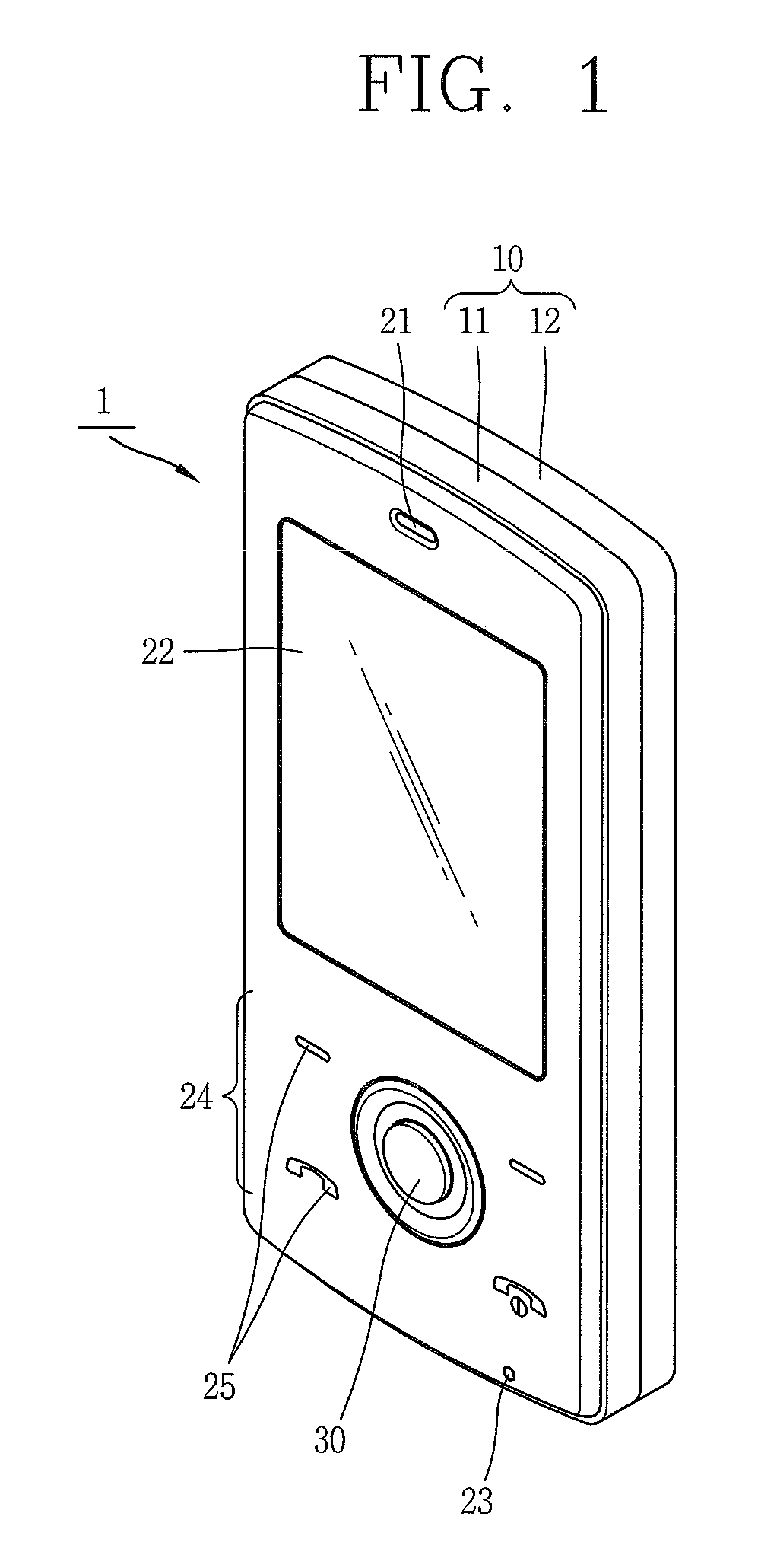
[0036]FIG. 1 is a front perspective view showing a portable terminal according to the present invention.

[0037]As shown in FIG. 1, the portable terminal 1 comprises a terminal body 10 that forms the appearance, a display unit 22 for outputting visual information, an audio output unit for outputting voice or audio information, a user input unit 24, and an audio input unit 23 for inputting audio information.

[0038]The user input unit 24 includes key input portions 25 disposed at a plurality of positions, and an input device 30 for moving a pointer or a cursor and so on to a desired direction by being moved to a plurality of directions from the center position.

[0039]FIG. 2 is an exploded perspective view showing a front case of the portable terminal of FIG. 1.

[0040]As shown in FIG. 2, the terminal body 10 is divided into a front case 11 and a rear case 12. The front case 11 includes a window region 11a for implementing the display unit 22, and an installation hole 11b through which the i...

second embodiment

[0068]FIG. 8 is a front perspective view showing a portable terminal according to the present invention.

[0069]As shown in FIG. 8, the portable terminal 100 includes a first body 101, and a second body 102 configured to slidably cooperate with the first body 101 in one or more directions of the first body 101.

[0070]A status that the first body 101 is disposed to overlap the second body 102 is referred to as ‘closed configuration’, and a status that the first body 101 exposes at least one part of the second body 102 is referred to as ‘open configuration’.

[0071]Typically, the portable terminal 100 functions in a standby mode when in the closed position, and a call mode when in the open position. However, the call mode may be converted into a standby mode by a user's manipulation or lapse of a certain time.

[0072]A case (casing, housing cover, etc.) that forms the appearance of the first body 101 is formed by a first front case 111 and a first rear case 112. Each kind of electronic compo...


PUM


Abstract

An input device comprises: a circuit board having a magnetism sensing portion for sensing changes of magnetism; a magnet disposed above the circuit board by a prescribed height, and configured to move in a plurality of directions; and a shuttle having a magnet mounting portion for fixing the magnet at the center thereof, and having a plurality of elastic connecting portions radially disposed around the magnet mounting portion, the elastic connecting portions formed in curved lines from the center of the magnet so as to elastically support the magnet mounting portion.

Description

RELATED APPLICATION[0001]The present disclosure relates to a subject matter contained in priority Korean Application No. 10-2007-0103721, filed on Oct. 15, 2007, which is herein expressly incorporated by reference in its entirety.BACKGROUND OF THE INVENTION[0002]1. Field of the Invention[0003]The present invention relates to an input device for a portable terminal configured to move a cursor, a pointer, and so on, and a portable terminal having the same.[0004]2. Background of the Invention[0005]In general, a portable terminal serves as a portable device having one or more functions such as voice and video calls, information input / output, and data storage.[0006]As the portable terminal now provides many additional services beside the basic call service, a user can capture photos or moving images, reproduce music or moving image files, play games, receive broadcasting programs, and so on. The portable terminal is implemented as a multimedia player.[0007]In order to implement complicat...

Claims


Application Information

Patent Timeline
Patent Type & Authority Patents(United States)
IPC IPC(8): H03M1/22G06F3/0338
CPCG06F3/0338G06F3/0362H04B1/38
Inventor YOO, JOON-HEE
Owner LG ELECTRONICS INC
Learn More