
Collapsible projection screen systems

a projection screen and collapsible technology, applied in the field of collapsible projection screen systems, can solve the problems of difficult to provide a flat screen surface, and achieve the effects of reducing the difficulty of hoisting facilitating screen support, and lowering the screen

Inactive Publication Date: 2011-10-11
CREEL SILAS
View PDF24 Cites 9 Cited by
  • Summary
  • Abstract
  • Description
  • Claims
  • Application Information

AI Technical Summary

Benefits of technology

[0007]Advantageously, by providing a screen tensioning mechanism that acts in addition to the support arrangement, a generally flat screen surface can be achieved. In known collapsible screen systems, once the screen reaches a certain size it becomes difficult to provide a flat screen surface because of the inherent flexibility in the screen. The applicant has developed a screen tensioning mechanism which enables the use of large sized picture screens (eg. commensurate in size with permanent screen installations) whilst providing for projection screen portability. In addition, a tensioned screen can be provided which has greater resistance to air movements including wind, and is structurally more stable and strong.
[0054]Alternatively or additionally the drive apparatus can comprise a retractor drive connected to the trailing edge and adapted to urge the trailing edge away from the leading edge. The retractor drive can form part of a roller assembly onto which the screen is rolled when moving towards the collapsed position. In this regard, the retractor drive can comprise a spring mechanism in the roller assembly which is progressively tensioned when the screen is unrolled from the roller assembly when moving towards the erect position. The retractor drive alternatively or additionally can comprise a motor for acting on the roller assembly in a manner that causes the screen to be rolled towards the collapsed position, and which can be actuated to significantly increase screen tension.

Problems solved by technology

In known collapsible screen systems, once the screen reaches a certain size it becomes difficult to provide a flat screen surface because of the inherent flexibility in the screen.

Method used


Image

  • Collapsible projection screen systems
  • Collapsible projection screen systems
  • Collapsible projection screen systems

Examples


Embodiment Construction

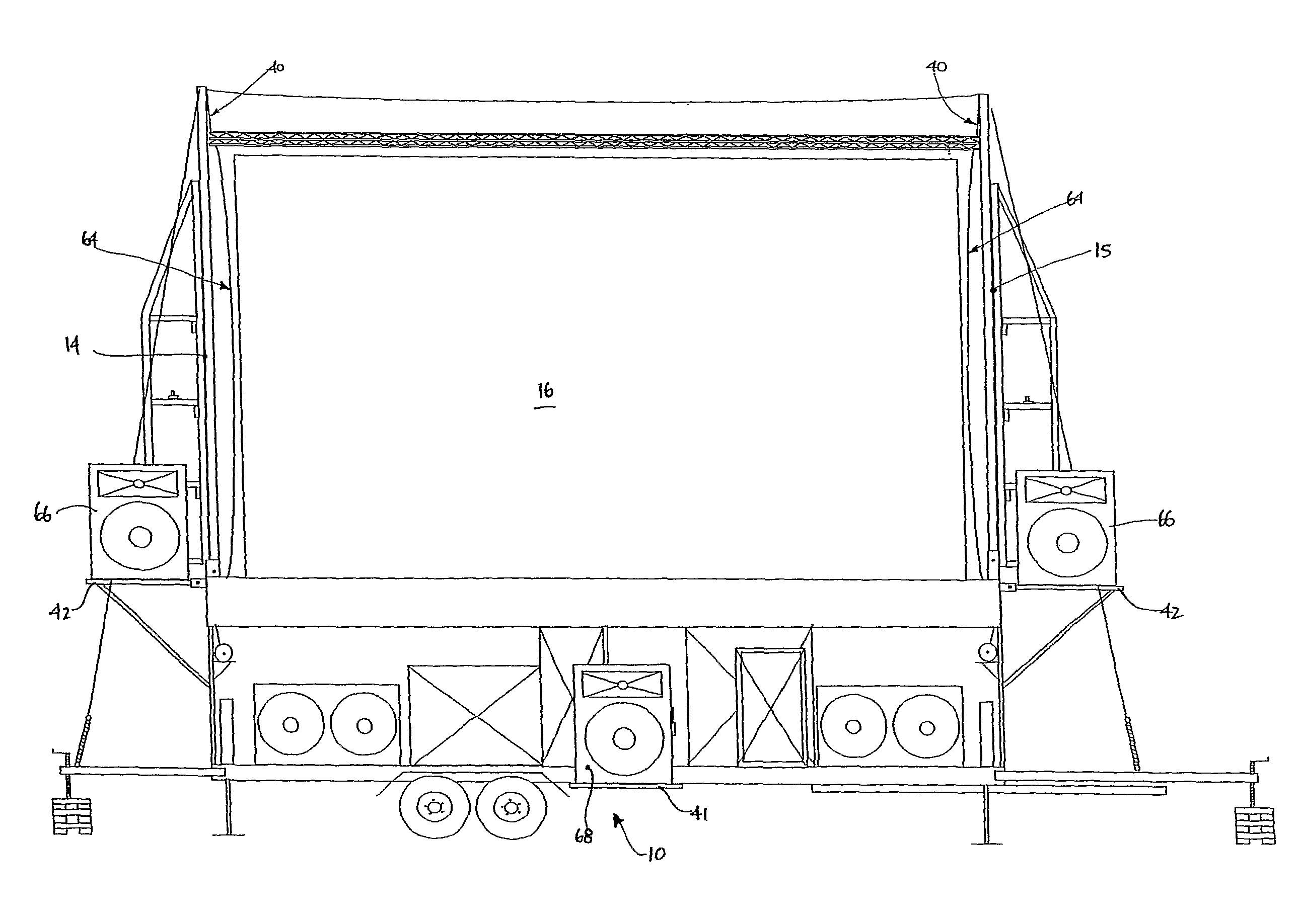
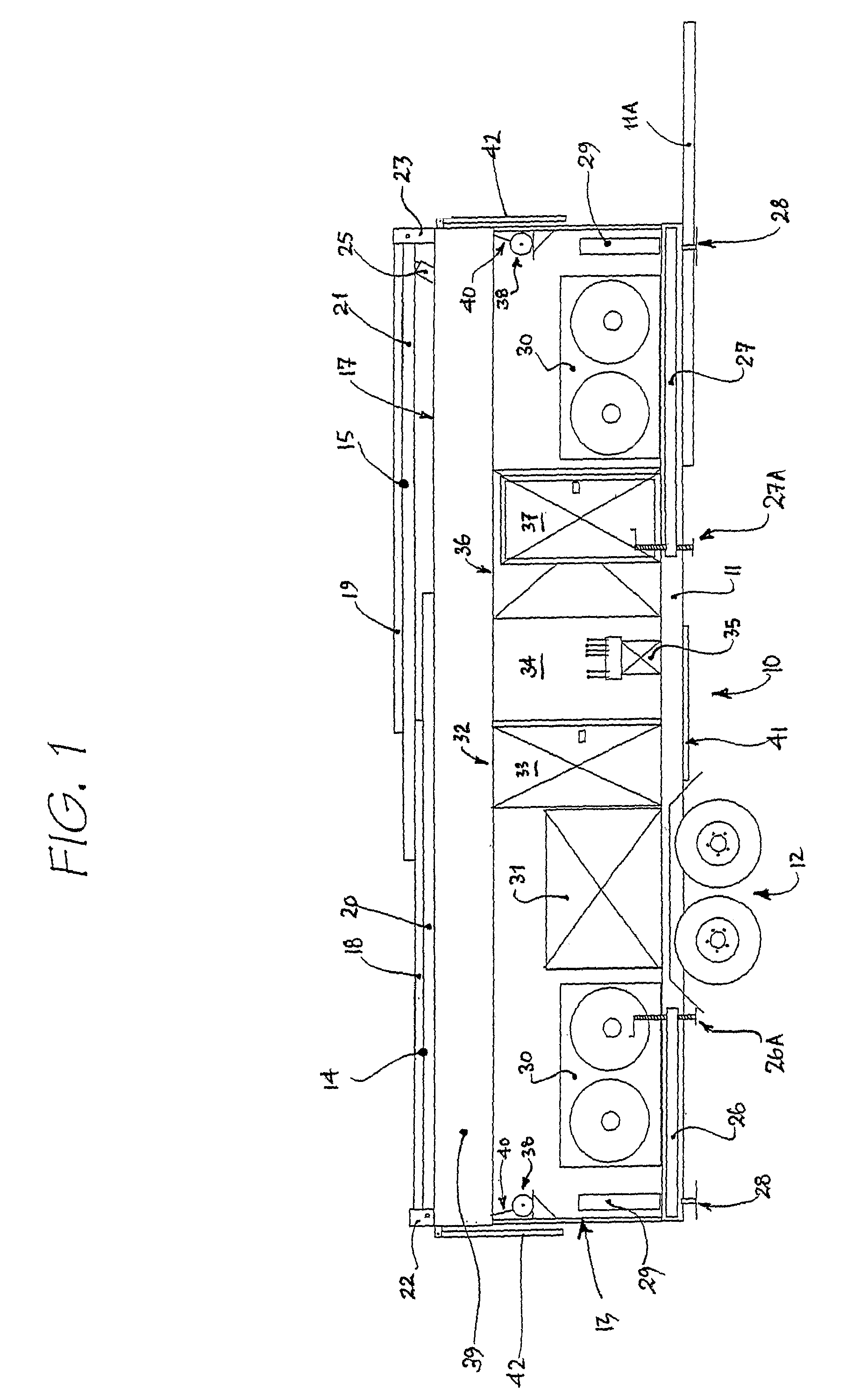
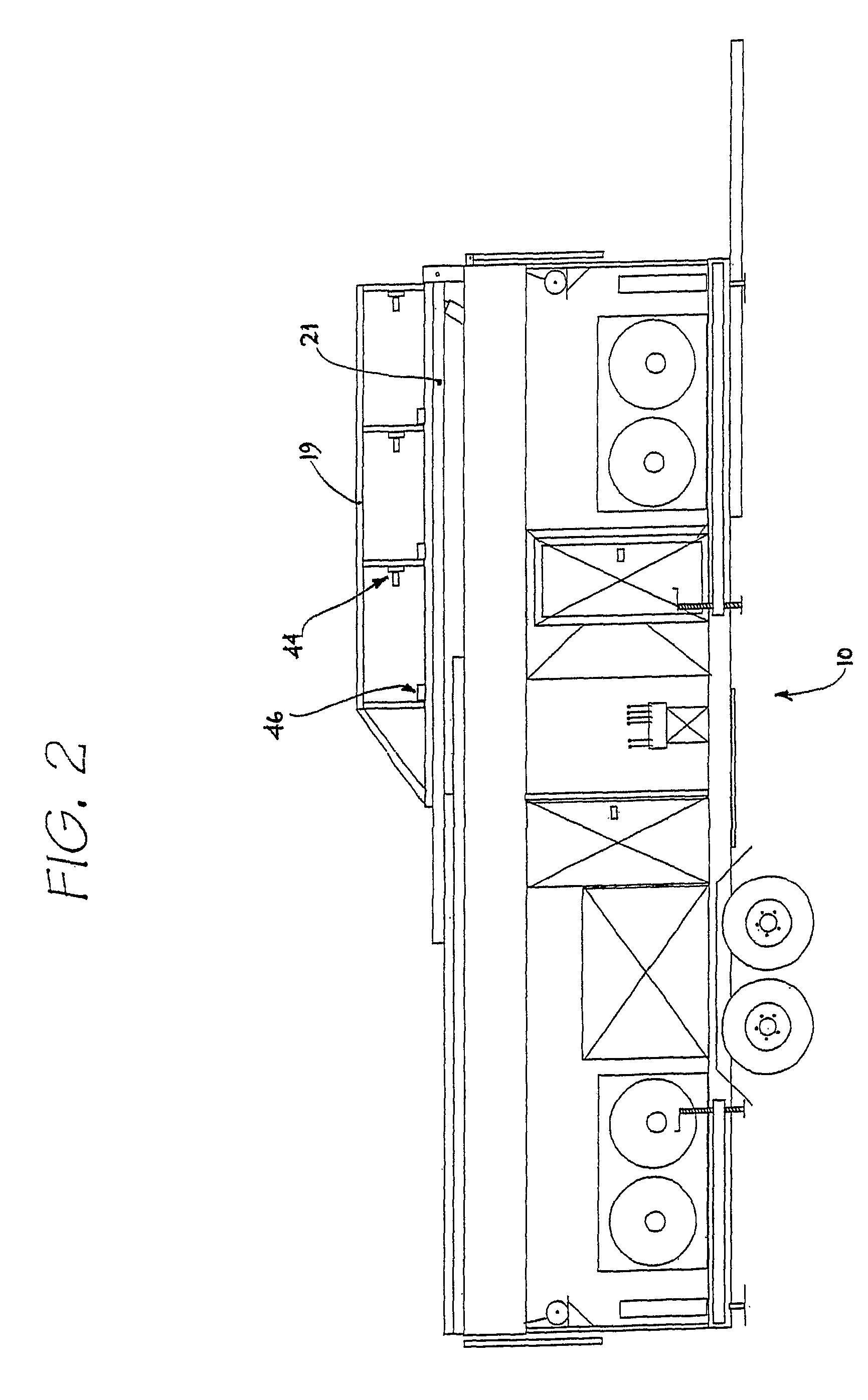
[0068]FIGS. 1 to 7 show the sequential erection of a collapsible projection screen system in accordance with the invention. FIG. 1 shows the system in its collapsed (transportation or storage) configuration and FIG. 7 shows the system in its fully erect (in use) configuration. Additional features of the assembly are shown in FIGS. 8 to 10.

[0069]As shown in FIGS. 1 to 7, the collapsible projection screen system typically comprises and is incorporated into a trailer 10. The system further comprises a chassis 11 to which is mounted a wheel assembly 12 and a trailer superstructure 13. A trailer hitch 11A extends from the chassis. Left and right screen support assembles 14, 15 are hingedly mounted to the superstructure 13 of the trailer 10 and are pivotable between a collapsed position as shown in FIG. 1 and a screen support position as shown in FIGS. 4 to 7. The system also includes a flexible projection screen 16, as shown in FIGS. 5 to 7, which is moveable between a collapsed position...


PUM


Abstract

A collapsible projection screen system mountable on or at a moveable carriage (10), the system comprising a flexible projection screen (16) moveable between a collapsed position and an erect position in which the screen (16) is supported by a support arrangement (14, 15), and a screen tensioning mechanism (64, 40, 56) operable on the screen (16) in the erect position to provide a generally flat screen surface. In another embodiment there is disclosed a mounting assembly for a flexible projection screen in a collapsible projection screen system having a roller, a mechanism for applying tension across and between a leading edge and a trailing edge of the screen in the erect position, the mechanism comprising a braking device and a drive apparatus.

Description

CROSS-REFERENCE TO RELATED APPLICATION[0001]This application is a U.S. national stage entry under 35 U.S.C. §371 of PCT International Application No. PCT / AU2004 / 000619, filed on May 12, 2004 and published in English as International Publication No. WO 2005 / 109092 A1.FIELD OF THE INVENTION[0002]The present invention relates to improvements in collapsible projection screen systems, typically (though not exclusively) screen systems used in outdoor projection applications including outdoor cinemas, concerts, rallys, advertising, signage etc.BACKGROUND TO THE INVENTION[0003]The applicant has previously developed a collapsible projection screen assembly, which is disclosed in patent application number 87307 / 01. The applicant has now made improvements to this screen assembly.SUMMARY OF THE INVENTION[0004]According to a first aspect of the invention there is provided a collapsible projection screen system mountable on or at a moveable carriage, the system comprising:[0005]a flexible project...

Claims


Application Information

Patent Timeline
Patent Type & Authority Patents(United States)
IPC IPC(8): G03B21/56
CPCG03B21/58
Inventor CREEL, SILAS
Owner CREEL SILAS
Learn More